Foreword:
This page is a primer on what's required for basic installations. It will not be a step by step installation manual. It will describe some basic upgrades and what's involved for basic installations. Since this is at the beginning of the directory and some of the terms have not yet been covered, there will be links to pages with more detail about each new term. Hopefully, this page will help you to make more educated decisions when you buy and install your equipment.
This page is quite long but if you're intent on installing your own system and you're new to car audio, take your time and read through all of it at least once.
Choosing the Right Components:
Before you can choose the right audio components, you need to decide what you want from your audio system. Some just want to upgrade from an old stock stereo to a head unit with a CD player or interfaces for their USB flash drives or MP3 players (iPod, etc...). Others will want a full blown competition system. Some want quality (clean, accurate sound). Others want quantity (loud, heavy bass...). If you only want to buy your equipment once and be done with it (well.. at least for several years), think about what you want. A lot of people buy equipment without any forethought and are dissatisfied with the results.
Speakers are, by_far, the most critical, variable component. For the most part, amplifiers and head units sound relatively similar among the better brands (Pioneer, Alpine and Kenwood...). Speakers, on the other hand, are very different from brand to brand (or even between the different product lines from the same manufacturer). There are a lot of cheap/inexpensive speakers out there. Many sound really bad. Some are pretty decent. Don't let the sensitivity/efficiency of a speaker cloud your judgement. It's common for a speaker to seem to sound better if it's louder but after careful listening, it becomes obvious that the loudest speaker isn't always the best sounding speaker. If you're on a budget (most of us are), the trick is to go listen to the speakers. It's less critical if you're spending $300-$400 on a pair of high end component speakers like those from Quart, Morel or Focal because most of them are good quality with good frequency response.
When you go to audition speakers, go with a well recorded CD (preferably one that you know well). I recommend a CD because it's most likely to be usable on the widest variety of head units. Visit as many stores as possible. In each store, find a high quality head unit (Alpine, Pioneer, Kenwood...) and set all of the tone controls to flat (zero). Turn off any DSP such (ambience, theater, hall effect...). Also turn off any other equalization (BBE, parametrics...). This will give you a chance to listen to all of the speakers with essentially the same signal in the various stores you visit. If possible, listen to all of the speakers using the head unit's internal amplifier. This will ensure that you're listening to the same power output in all cases. The internal amplifiers on most all of the head units in production produce approximately 20 watts per channel into 4 ohms no matter the power rating on the deck. Listen to the speakers to see if there are any peaks in the frequency response (the peaks will cause certain parts of the audio spectrum to be annoying). If there are, go to the next set of speakers (peaks that are easily noticed will be hard to get rid of - even with a good equalizer). Find a set of speakers that have good full range sound without any annoying peaks and no significant dips in their frequency response. If necessary, take notes. Include the model number and brand of speakers and any likes or dislikes.
Above, it was recommended that you listen to the speakers with only the head unit's internal power amplifier (no external power amplifier). This is to allow an apples to apples comparison. If you intend to use an amplifier, especially if it's going to drive the speakers to their limits, you should also listen to them with an amplifier with similar power ratings to the one you are going to use with them.
If you can't find the speakers that you want to buy locally (and therefore can't listen to them before buying them), there are a couple of things that you can do to help ensure that you don't make a purchase that you'll regret. Find a forum where there are threads about the speakers that you're interested in. You can use Google to find these. Look at the reviews online. Professional reviews are generally more reliable but don't completely disregard reviews from individuals. Try to find results from car audio competions, especially those that are skewed towards the type of listening that you intend to do (heavy bass, sound quality...). If the speakers that you are interested in are in many of the winning vehicles, it's likely that they are high quality speakers.
If you intend to use a head unit with your iPod or with a USB flash drive, you should take them with you. If possible use them with the head unit that you're interested in. This may not be possible with the iPod because it may require an optional cable but most USB ports are on the front of the head units. Some head units will have better interfaces than others and you don't want to buy a head unit that is difficult for you to use with either device.
Train Your Ears:
This next section may seem out of place but it's important, especially if you want quality over quantity. If you want to make good choices, you should know what 'good' is. If you've never heard good frequency response, find a high end home stereo demo room (there may be one in the same store in which you're auditioning car speaker). They will be able to play your CD through home speakers. Good quality home speakers will have a good flat frequency response. Look for brands like Polk, Infinity, Paradigm. Listen to speakers 'without' internal amplification (such as those with built-in powered subwoofers) and with woofers no larger than ~8". Speakers with dual 6" woofers are often a good choice. Again, tell them to set all of the equalization/tone/processing to flat or off (using an amplifier that doesn't have any digital processing and actual knobs for bass and treble will help assure that you're listening to a 'clean' signal). Listen to your favorite song on the CD a few times to help you remember what it sounds like. Notice the relative level of individual instruments (compared to the other instruments and the vocals).
If you're not on a really tight budget and can afford to spend an extra $90-100, buy a nice pair of headphones to help train your ears to know what truly good sound is. I'm not talking about the junk that's sold with most MP3 players (sorry for those who are offended). My preference for budget headphones is the Sennheiser HD280 Pro. When most people (who only know what cheap headphones sound like) first listen to them, they don't like them because they don't have the exaggerated bass of most headphones. What you get is a good flat response from one end of the spectrum to the other. 'Flat' is a term to describe the frequency response. It means that there are no big dips or peaks in the response. Flat is good. One advantage of using headphones is that you can take them with you to compare them to the speakers you're listening to (if you're using an MP3 player as the signal source or have a copy of the CD on an MP3 player).
For a suggestion of what to use as source material (good sound quality), try the following tracks. If you have Rhapsody, these are all available (or they were, the last time I was there). If you want a Rhapsody playlist that includes most of these tracks (and quite a few others), email me. If you download these in MP3 format, choose the ones with the highest bitrate possible. Flack or wav format is better than most MP3 files but high bitrate MP3 files are OK.
James Newton Howard and Friends:
04-L'Daddy (you probably already have this one)
Joe Cocker (from the Sheffield Steel CD):
09-Talking Back To The Night
06-Ruby Lee
07-Many Rivers To Cross
Joe Jackson:
You can't get what you want
Van Morrison:
02-Philosopher's Stone
The entire CD is pretty good
Also try...
Renee Olstead (from the album of the same name):
Summertime
Eva Cassidy (from the Wonderful World album)
What a wonderful world
Not very dynamic but nice SQ...
Roy Orbison (black and white night)
Only the lonely
Aaron Neville (The Very Best Of Aaron Neville)
The Bells
Oh, yeah... Don't forget to take your CD or flash drive when you leave each store. :)
OEM System Upgrades
OEM Systems:
Most all vehicles come from the factory with a stereo system. The least expensive have an AM/FM radio (no CD) and 2 speakers. Most will have a CD player and 4 speakers. Since most head units drive the speakers directly (no external power amplifiers) they have to have internal power amplifiers. These amplifiers are limited in power and may not provide enough power for some. For those that don't know, OEM stands for Original Equipment Manufacturer. It simply means that the radio was supplied by the manufacturer of the vehicle.
OEM Systems with External Power Amplifiers:
There are quite a few manufacturers that have high end audio systems that use external amplifiers. Sometimes there's only one external amplifier which is used to power an OEM subwoofer. Many times, this amplifier is mounted under the rear deck. If the system uses external amplifiers for all of the speakers, the amplifiers are mounted under the seat, in the doors or in the trunk. Sometimes, the external amplifiers are needed because there was no room in the head unit for amplifiers. Other times it's so that they can provide more power to the speakers than you can get with an internal amplifier. This was the case with the Bose® systems. They used switching (class D) amplifiers and low impedance speaker to provide as much as 80 watts (of RMS power) per channel to the speakers. If you're upgrading the speakers with this type of system, many times, it's much more expensive than with other systems. Since the amplifiers are designed to work exclusively with the low impedance speakers, they will not work well with the new speakers. Even if you do use the stock amplifiers, the output may be significantly less due to the higher impedance of the new speakers. When upgrading from this type of system and you want to retain the stock head unit, you'll generally need a special adapter to get a usable preamp level signal from the head unit. You'll need an amplifier with enough output channels to drive all of your speakers and you'll need new speakers.
Many of the newer OEM systems use a data bus system that makes installation a bit more complex than it was in some of the older vehicles. For example, when installing a new head unit, there may not be a switched wire to tell the aftermarket to switch on and off with the ignition switch. In other vehicles, the OEM head unit is an integral part of other systems like OnStar or the warning buzzer/beeper that tells you that the door is open, for example). For virtually every vehicle, there are interface modules that allow you to replace the OEM head unit with an aftermarket head unit. These, however, can get expensive. Some are as much as $150. You can check with interface manufacturers like Scosche or Pacific Accessory to see what's needed for your vehicle. Many people won't deal with Crutchfield because they feel their prices are too high but they have excellent customer and technical support. If you like DIY and are not searching for bargain-basement prices, Crutchfield is often a good choice.
Starting From Scratch
Basic Requirements:
If you have no audio equipment in your vehicle, you'll need (at least) a head unit and a pair of speakers. Virtually all aftermarket head units have internal amplifiers. The exceptions are generally the top_of_the_line models. If you plan on upgrading to a system in the future, you'll want a head unit with at least one pair of preamp level (RCA) outputs.
Features:
Most people want certain features on their head units and that, along with cost, will determine the head unit that they buy. There are a few things that I will recommend.
No motorized face. They have significantly more problems than rigid faced units. Even flip down faces have more problems than the rigid faced units. If you have to have a deck with a motorized face, get an extended warranty.
Remote controls... Many think a remote is for those who are too lazy to reach for the radio. A remote control has a few significant advantages. They are safer because you can make changes without having to take your eyes off of the road. They also reduce the wear and tear on your head unit. Most head units have very small (sometimes cheaply made) switches for volume, track, station preset and such. If you repeatedly push these buttons with more force than necessary, they will fail. Some fail within a year. Replacing these small switches can be expensive. Using the remote allows these switches to last much longer and also allows the face plate around the buttons to remain as new. If the switches in the remote wear out, the remote can be replaced for less than the cost to repair the face of the head unit.
RF Modulators:
When adding certain accessories like a CD changer or an MP3 player or a satellite radio receiver to an OEM system (or any system without an auxiliary input), you need some way to get the signal into the audio system. Since very few head units have auxiliary signal inputs, there's generally no direct preamp signal level input path. That's where the RF Modulator comes into play. The RF (radio frequency) modulator is essentially a micropower radio station. It basically takes an audio signal and mixes it with a radio frequency signal. This allows the signal to pass through the tuner (where the RF part of the signal is stripped from the audio signal) and into the audio stream. You tune your radio to one of two (or more) selectable channels (the frequencies are determined by the designer of the RF modulator) to hear the signal. It's not quite as good as having a direct preamp level input signal path but it's generally pretty good. Crutchfield generally has a few different models from which to choose.
RF Modulated Changers:
Some CD changers are designed to be used with RF modulators (some work 'only' with modulators). For these changers, you'll generally have a small display that mounts on or near the dash. The controller is generally connected to the changer by a special multi-conductor cable that has to be run from the changer to the controller.
Tools
Not having the proper tools can make a simple job almost impossible. In this section, you'll see a few of the most important tools and suggestions for the various items that you'll need to install your system.
Crimping Tools:
Below you see 2 different styles of crimping tools. They are different in several ways. The one below is a very heavy duty pair made by Thomas and Betts. They're a bit beat up but they're probably 25 years old and still work perfectly. As you can see, the end is made for cutting (and stripping). The section closer to the pivot is made for crimping. In this case, these are made for crimping UNinsulated terminals. They will work for insulated connectors but they generally destroy the insulator.
The second second pair of crimpers is also heavy duty. They can properly crimp either insulated or uninsulated connectors. To strip with the crimpers above or below, you simply apply enough pressure to cut through the insulation and then (with the jaws still clamped on the wire) pull the insulation off of the end of the wire. If the insulation is tough, cut through the insulation, turn the wire 90� and cut through the insulation again. Then pull the insulation off of the wire. For wire that's really difficult to strip, wrap the wire around your hand (to prevent it from slipping through your hand) and use you thumb as a fulcrum to help pull the insulation off.
The pair below is a somewhat less robust type of crimping tool and will bend if you apply too much force. You can see that there are several oval shaped spaces in the tool. These are for crimping insulated terminals.
Expect to pay between $20 and $30 for a good pair of hand crimpers (the cheap pair immediately above - they cost less than $3 - are not for professional installers). For very large wire, there are different types of crimpers. Some are used with a hammer to crimp the terminals onto the wire (one example can be seen on the Battery Isolators page). Ratchet crimpers (below) ensure perfect crimping because they have to crimp to a precise thickness to complete the cycle and remove the crimp connector from the tool. The ones below can be found online. Search for:
902-089 crimper
Multimeter:
A good multimeter is required for most car audio installs. You'll have to measure the voltage, check for continuity, measure resistance... Don't make the mistake that too many new installers make and buy an extremely expensive meter. Having a meter with more features than the rest of the installers doesn't make you a better installer. A good installer needs a durable, accurate and reliable meter. I strongly recommend Fluke meters. They're more expensive than most other meters but that's because they're better than most of the cheaper meters. If you're on a tight budget, try to find a used one in good condition. You can find them in Pawn shops and of course, on eBay. If you decide that you want a meter with more features later, you can buy one. Having a second meter will give you a 'back-up' meter if something happens to the meter you use most of the time.
Drill Bits:
One of the most commonly used bits is the step-bit or Unibit. These are relatively expensive (expect to pay $30 each for good quality bits) but they're required for drilling large holes, particularly in the firewall, for grommets. You'll need a set of standard twist bits also but a set of 8 or 10 bits will be enough.
Cordless Drill/Driver:
You'll need a cordless drill or driver. In general, if it has a 3-jaw chuck on it, it's considered a drill. If it has a 1/4" bit holder, it's considered a driver. Here, a small, powerful drill/driver is what you want. It will need to get in tight spots so you don't want anything too large. The quality of this type of tool can vary greatly from year to year so I'd suggest asking other installers what they recommend. Some have problems with weak batteries or chargers. Others have mechanical failures. Bad switches plagued some brands for years.
You'll also need a set of 1/4" driver bits. Initially, a set with most of the common types of bits is a good choice but after a while, depending on which types of vehicles you see the most, you'll see that you need other bits. This bit set (Milwaukee 48-32-4401) has a tray to hold miscellaneous bits that didn't originally come in the set.
If your budget for tools is relatively low, the following are probably the most bang for the buck. The first is a 10 in one screwdriver. The #2 Phillips bit, the 5/16 nut driver (for 8mm bolts) and the T-15 Torx bit are going to be the most useful for installs.
The next assortment of tools is a bit more flexible. The bits are standard 1/4" inserts so you can replace the ones that are not commonly used for those that are more commonly needed. The bit carrier is stored in the handle. The 1/4" hex to 1/4" square adapter will allow you to use it with sockets. It's important that you get a 1/4" driver handle with a lock that holds the bits securely. The standard magnetic holder is OK for casual use but it will result in lost bits. This is common when you're carrying it (they fall out) or when you tighten the last Phillips screw and you don't notice that the bit has stuck in the screw.
For screws that are really tight, you may also need a 1/4" drive ratchet with a 1/4" socket or a ratchet like the one below.
For tight spaces, you may need a right angle screwdriver. The following are the cheapest and probably the most common. The ratchet above can be used with 1/4" hex bits and can get into many places a screwdriver cannot.
If you have a bit more space to work in and a bit larger budget, the following makes removing screws in tight spaces a bit easier. Skewdriver is the most well-known name for these but there are other manufacturers. This one came from Lowes.
The following is a set of tools used to pry off the various panels and trim pieces in a vehicle. Most of the panels are made of material that's easily (and permanently) marred if you apply too much pressure to them. These tools are softer than screwdrivers and typically have a wider area of contact so they aren't as likely to damage the panels. This set of tools is from Harbor Freight (part #: 67021). They were recommended by a professional installer. The Harbor Freight part number 95214 was another set recommended by professional installers.
The lighting under the hood and dash isn't very good in most vehicles. This means that you will need to use a lamp or flashlight to see many of the connectors. If you're somewhat far sighted (can't see well up-close), you can buy lighted reading glasses. You can purchase a pair (Foster Grant LightSpecs) from Wal-Mart. They have LEDs for illumination and work well for close-up work. If you buy this type of glasses, you need to buy the ones best suited to your eyesight. They also use batteries relatively quickly so turn them off when you're not using them. If you use a lot of batteries, buy them on eBay.
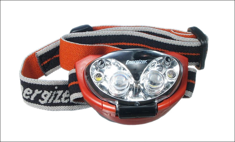
Another option is a headlamp like those used by campers or hunters. The following is an inexpensive headlamp. They're good enough but the quality of the LEDs isn't great (inconsistent color and pattern). If you have other uses for a good headlamp, something like the Fenix HP11 is good. With the diffuser, it produces a very white, even field of light.
Connectors
There are many types of connectors that can be used for car audio. I'll cover just a few here.
Butt Splice Connectors:
The most common connector is the butt splice connector. It is generally a copper tube covered with a PVC insulator. As you can see in the photo below, the butt connector has a bell on each end. This allows for the larger diameter of the insulation and acts as a bit of a strain relief. The point where the bell tapers is where the actual copper conductor/connector begins on the inside. The black outline shows the approximate size of the copper tube inside the insulator. The middle of the tube has a 'stop' to prevent inserting the wire too far. The other end of the white wire is stripped the right amount. The amount of bare wire isn't real critical but it should ideally go to the center stop point and not allow any of the copper to show at the point where it enters the connector. You'll notice that the insulator is RED. This indicates that it is designed to accept a certain range of wire sizes. Red connectors are designed to accept wires between 22g and 18g. Blue connectors are for wire sizes 14g to 16g. Yellow connectors are for 12g to 10g. For larger wire sizes, the colors start over again but the difference in size is so significant that you'll never be confused on which wire a given color connector is to be used.
Closed End Crimp Caps:
Many installers use closed end connectors with good results. For this type of connector, you strip the wires, twist them together, place the cap over the twisted wire and crimp it. They're especially good when you need to connect more than 2 wires. They may be better (less likely to pull apart) than butt connectors for newbies. The biggest problem I find is that it's not as easy to make a nice, neat wiring harness with them. Other than that, they work fine. In the drawing, the cap has already been crimped. The dashed lines show the uncrimped dimensions.
Spade and Ring Terminals:
Below is an assortment of ring and spade terminals. These also use color coding to indicate the wire capacity. The closed terminals are 'ring' terminals. The forked terminals are 'spade' terminals. The center terminal on the bottom row is a spade terminal designed to hold the terminal block's screw so that it doesn't slip out when tightening the screw on the terminal block. These are good for when you're working in tight spaces. The large ring terminal is used for 6g wire. As I said above, the colors repeat. Even so, you're not likely to get it confused with terminals designed for 14-16g wires. The yellow terminal is a standard ring terminal that's designed to work with 12-10g wires. All of these terminals have at least 2 important specs. The wire size with which it is to be used and the screw or stud size that it can accommodate. The second image shows how the terminals are sometimes marked to show wire size.
Push-on Terminals:
This type of terminal is used on most speakers. In the Photo below, you can see that one is fully insulated and one in uninsulated. If you were using them in-line (one female push-on and one male push-on - both on the ends of wires), the fully insulated would be the best choice. For speakers, the uninsulated terminal is often preferred because it allows you to push it farther onto the speaker's terminal (the insulator doesn't get in the way).
In the image below, you can see a push-on terminal and two arrows. The green arrow highlights a small protrusion. It's purpose is to lock the terminal onto the male terminal. You've probably noticed that there's almost always a hole in the middle of the speaker terminal. It's there for this lock to fall into. The red arrow highlights the wire stop. It simply prevents the wire from going too far and possibly preventing the terminal from fully sliding onto the speaker terminal.
Wire Nuts:
Many people use wire nuts when installing their stereos simply because they're readily available. For most all situations, wire nuts are not a good idea for car audio. When used for household wiring, they're used to connect 2 or 3 individual solid wires (not stranded like those generally used in car audio) in a vibration free environment. This is much different than in a vehicle. Wire nuts don't hold well on finely stranded wire and will eventually work loose. The photo below shows the inside of a wire nut. This one has 2 threaded sections. The bottom is plastic and is designed to grab onto the insulation. The top has a metal wirewound insert that grabs onto the copper. If you were going to wire your house, this would be a good choice. For a car, it's a bad choice.
Scotch-Loks and T-taps:
The next 3 images are of a 'Scotch lok' type in-line tap connector. Scotch Loks are used where you need to tap into a wire but don't want to have to cut it. They are most commonly used in situations like splicing in a boat trailer connector. You can tap into the brake and running lights without having to cut the wires. Some believe them to be completely unreliable but when you use the right size connector for the wire you have, they are very reliable. They are also color coded for wire size. As you can see, there are 2 slots for wire. One slot goes all of the way through. It's for the wire you're tapping into. The other (for the new wire) has a stop (at end of red arrow). You put both wires into the connector then use a pair of pliers to push the metal piece all of the way down. The 'W' shaped piece of metal cuts through the insulation of both wires and electrically connects them. After the metal connector is all of the way down, you close the cover to insulate the metal tab. If these are going to be used in wet environments, they should be filled with a silicone dielectric grease to prevent corrosion.
T-taps work in essentially the same way but instead of connecting the wires directly, they provide a terminal to be used with an insulated male push-on terminal. The image below shows a T-tap open and closed with a male terminal. The tap would of course be closed completely before inserting the connector.
Soldering: Soldering is probably the most secure way of connecting 2 wires (if it's done properly). The photo below shows an in-line solder connection. The wires were stripped back approximately 3/4". Each wire was then bent, roughly, into the shape of a fish hook. They were then 'hooked' onto one another and the end of the wires were twisted back around themselves. They were then soldered together. Both physically and electrically, this is a very strong connection. Of course, this method requires that we insulate the connection. Here I used heat shrink tubing to insulate it. I could have also used electrical tape. The second image is a close-up of the solder joint. The little yellow drops are solder flux. When soldering wires, you have to make sure that the solder is made for electrical connections. The flux used in solder intended to solder copper pipes is too aggressive and will corrode the wires.
The image below shows two pieces of wire with ring terminals. One is only crimped (which provides a very good connection). The other is crimped and soldered. This provides an electrical connection that's about as good as it can get. One thing that you should keep in mind. Solder has a fairly high resistance compared to copper. This means that you shouldn't rely on solder alone for a good connection. It has to be crimped also. Notice how well the solder flowed. It actually flowed back under the insulation. To do this, you need a very hot iron. A propane torch won't work well because it causes oxidation and will not allow the solder to 'stick'. The solder will just roll off of the oxidized copper. If you have to use a propane torch, heating the terminal from the back side (opposite the wire) will reduce the oxidation of the copper.
Connector Quality:
There are many low quality connectors on the market. Many of the types you get in cheap connector sets (with cheap crimping pliers) are made so cheaply with so little metal that they can NEVER make a good crimp. These are some other things that make good quality connectors. The best connectors have all of these features.
Funnel Entry Insulators:
Funnel entry is simply where the insulator forms a funnel inside of the insulator so that the wire doesn't catch on the edge of the copper connector as you insert the wire. If you are going to make a lot of connections, this is absolutely necessary. In the image below, the connector on the left has a funnel entry. The one on the right does not.
Nylon Insulators:
Nylon insulators are somewhat tougher than PVC insulators. When crimped too hard, PVC often splits or breaks up. Nylon is much less likely to split or break apart. In the image above, the connector on the left has a nylon insulator. The one on the right has a PVC insulator. Nylon insulators will generally be somewhat translucent. The PVC insulating material is opaque.
Brazed Seams:
When most connectors are made, they are stamped from a flat sheet then formed to make a round connector. When this is done, the part where the 2 pieces meet can be left as_is or they can be brazed or soldered together. When this is done, it provides for a much more secure crimp (because the seam can't pull apart - which would relieve pressure on the crimp/wire). In the next image, the center terminal has a brazed seam. The one on the left did not. As you can see, when pressure was applied to only half of the connector on the left, the seam opened up. The brazed seam on the center one was so strong that it actually deformed the other half.
More Information on Installing Large Terminals/Lugs:
If you're going to be installing a system that requires very large wire, you'll need to use special tools and techniques to get the best connection. The bottom of the Battery Isolators page has more information on installing large lugs.
Basic Head Unit and 2 Speaker Installation:
This page will deal mainly with the electrical aspects of an installation. Physical aspects like mounting and bracing won't be covered in any detail. OK, these are the electrical connections that will have to be made. This assumes that there was an OEM stereo in the vehicle and it did NOT have external amplifiers.
Ignition (switched 12 volt source - goes on and off with the key)
Ground
Left Speaker +
Left Speaker -
Right Speaker +
Right Speaker -
Power Antenna Remote (if the vehicle has a power antenna)
Antenna (aerial)
All of these connections should be made using butt connectors and an aftermarket wiring harness adapter (shown on the 'head unit' page). You'll connect the new head unit's wires to the adapter harness. This will allow you to make all connection while leaving the stock harness intact. Some vehicles require antenna adapters. Check with your car audio dealer to see if you need one. If you have an older vehicle, it may have common grounded speakers. If this is the case, you will need to run new wires to the speakers. If in doubt, run new speaker wires. If you run new speaker wires, you'd connect the speaker output wires from the head unit directly to the new speaker wires.
Things You'll Need for a Basic Installation:
Strippers/Crimpers
Butt Connectors (red are most commonly needed for OEM wiring)
Speaker Wire (16g parallel zip cord is fine)
Tools to Remove the Head Unit (#2 Phillips screwdriver, 7mm nutdriver, a Torx T15 driver and a broad tipped regular screwdriver will get you a long way)
DIN Radio Removal Tool* ('U' shaped tool required to remove many of the newer car stereos - particularly Ford and Mazda)
*These tools are inserted into the 4 holes on your head unit (2 on each side). After inserting them, you pull them apart (away from the center of the head unit) and out toward you. Make absolutely sure that you've NOT inserted the tool on the radio side of latches. They MUST go to the outside of the spring latches. If they go to the between the radio and the spring latch and you bend the latches too far out, you may have to tear the dash apart to get the head unit out. The following demo may help.
----- Critically Important -----
Flash graphics viewing/use alternatives:
Flash support by most modern browsers has been dropped but that's not the end of the line for Flash.
There is no practical alternative to Flash for the interactive demos/applets/graphics on this site.. Especially when there are alternatives, some simple, some good, some...
Ruffle is chosen by most because they can't imagine using anything but their preferred browser. It works. It's OK but not great. The Flash graphics won't look as they're supposed to but it, generally, works.
The #1 preferred (by me) way to view the site and the Flash graphics is with the Chromium Portable browser and the installation of the older (no time-out) Flash Player files. This was incredibly simple when people knew computers but not today when people only know how to work with their phones.
The Flash Browser is a good option but it's so stripped down that it makes it somewhat difficult to use.
The Maxthon browsers are an option. The v4.95 is the easiest (install and use). V5.3.8 and 6.1.0 require (very) slightly more effort (very).
The Chromium and Maxthon browsers on the page above are 'portable' browsers. They are not installed into your system. They are simply made available for use on your computer. They can be carried around on a Flash drive and used on any computer.
----- Critically Important -----
Adding an Amplifier:
If your head unit has RCA/preamp outputs, adding an amplifier will be pretty straightforward. It will take a little effort but nothing really too difficult. The hardest part is running the new power wire from the battery to the trunk (boot) of the vehicle. And no, you can't connect the amplifier's main power wire to the vehicle's fuse box. These are the additional connections that you'll have to make:
Main Power Wire:
The main power wire must be connected to the battery. It must have an appropriately rated fuse in line (near the battery). The wire will have to pass through a grommet in the firewall, under the carpet and (generally) into the trunk. To get the wire into the trunk, you may need to remove the back seat. When you run it into the trunk, it generally has to pass over some sharp sheetmetal. If this is the case, take a piece of rubber heater hose and split it open. Open the hose and place it over the sharp sheetmetal. This will prevent it from cutting the wire. When making the connection to the battery, you'll usually use a large ring terminal. From the ring terminal you'll use a short length of wire to connect to the fuse holder. From the fuse holder, you'll run the power wire to the rear of the vehicle. In the rear of the vehicle, the power wire can be run either directly to the amplifier's positive terminal (if you have only one amplifier) or to a distribution block (if you have multiple amplifiers).
Signal:
The amplifier needs some sort of signal to amplify. The best way to send it a signal is through the RCA cables. If your head unit does not have preamp outputs, I'd recommend using a Line Output Converter (LOC). Since you may not have any troubleshooting skills, the LOC is probably the best way to avoid trouble. Many times, the speaker level input of an amplifier will be poorly designed and will cause noise problems. There have even been a few speaker level inputs on amplifiers with a common ground input (very bad). Using the LOC avoids these problems.
Remote Power:
The remote wire from the head unit tells the amp when to turn on and off. It is a low current control signal that runs from your head unit to the amplifier. It must be fused behind the head unit with a 0.5 amp fuse (1/2 amp).
Ground:
The ground from the amplifier will be a short run of cable approximately the size of the amplifier's incoming power wire. It will be grounded to the floor pan of the vehicle. The amplifier page has more details on getting a good ground.
Speaker Wires:
The speaker wires will run from the amplifier outputs to the speakers. For connecting the amplifier to woofers in the trunk, a short run of 16g speaker wire will be fine. If you're connecting the amplifier to interior speakers (doors, dash, back deck), you must make sure that there are no inline OEM amplifiers. If there's any doubt, run new wires.
Note:
Any speakers that will be connected to the amp MUST be disconnected from the head unit. Sending the amplifier's output signal back into the speaker outputs of the head unit will frag the head unit (at least a $90 repair bill).
Multiple Amplifiers:
When using multiple amplifiers, you'll have to do as above but a few more things come into play.
Power Wire:
The power wire will probably have to be larger. That's why it's good to look forward to what you want for your system. If you run a wire that's barely large enough for one amplifier, adding a second amp will require running a second wire (with its own fuse holder) or will require that you replace your existing wire. To find out what wire you need, you can use the calculator(s) on the 'wire' page of the site. You'll enter the total power and a few other things and they will tell you the proper wire size. To split the power source to each amplifier, you'll need to use a distribution block. I recommend fused blocks for splitting the 12 volt line and only UN-fused blocks for ground.
Fused Distribution Blocks:
The next image is the one from the Fuses page. This is a fuse holder but it's also called a fused distribution block. The fact that you can make multiple connections to another wire makes it a distribution block. Obviously it's called a fused distribution block because it has fuses. Fused distribution blocks are readily available with 2, 3 or 4 circuits (one fuse per circuit). These are only used for the positive supply side of the circuit. You don't want a fused distribution block on the ground side of the power supply. Some amps cause serious damage to the shield ground of the signal source (head unit) if they lose their ground (which would happen if a fuse would blow).
Un-fused Distribution Blocks:
For most stereo installs, you'll use a fused distribution block where the main power wire splits to go to the various amplifiers. This is because the wire size drops and you need to insert a fuse to protect the smaller wires (assuming that the main power wire is larger and is fused at the battery to protect only the main power wire). You should already know this because it was covered in detail on the Fuses page. For the ground, you will use an un-fused distribution block or simply ground all wires together. If you use a distribution block, you have several choices. The first one below is the type I like the best because you can get a better connection. The ones with a set screw (the second image below) don't always produce a reliable connection. When terminals are crimped and soldered and then bolted down tightly, you will have the best connection. Of course, this takes extra time and costs a bit more so most people opt for the set screw type distribution block. If you plan on using crimped lugs on large wire, read the Battery Isolators page. It has information on crimping and soldering the large terminals.
If you decide to ground all wires together, you should use ring terminals with a bolt, nut and lockwasher to fasten the ring terminals to the floorpan of the vehicle. If you use an un-fused distribution block, you will still have to make a connection to the floorpan and you would again use a bolt, nut and lockwasher. For the bolt and nut, use 5/16" or 3/8" diameter (or the equivalent for those outside of the US). When installing the nut on the bottom of the floorpan, apply a ring of silicone or an adhesive like Goop to help prevent water from getting into the vehicle If water gets through from the bottom, it will get between the connectors and the floorpan and corrosion will cause the ground connection to fail.
If you want a conductive sealer instead of an adhesive/sealant, you can use a compound like the one in the following photo. It's a bit messy. That's not a problem on the bottom of the floor-pan but when applying it to the top side, you should apply it sparingly.
Electronic Crossovers:
When using multiple amplifiers, you generally split up the audio spectrum. This allows you to send the bass to larger speakers and the rest of the audio spectrum to interior speakers. Many head units and amplifiers have built in crossovers and many of them are quite good but some are VERY poor. The poor ones generally have poor rolloff characteristics. Using a good quality external crossover solves this problem, It also puts all of the controls (level, crossover frequency, phase...) in one place. An external crossover also generally has more features than the crossovers built into the amplifiers. Head units sometimes have crossovers with a lot of features but require going through various menus, making adjustments and saving those settings. Some people like having a knob that they can see and adjust. This is where an external crossover is nice to have.
Signal:
When sending the signal to a single amplifier, you simply plug them directly into the amplifier. When you have multiple amplifiers, you have to get the signal to all of them. If you have only one pair of RCA cables, you can use y-cables. If you're using an external crossover, you can plug the RCAs into the input of the crossover. The crossover will then have multiple outputs. The low pass output will go to the bass amp. The high pass output will go to the highs amp. No y-cable will be needed unless you have multiple bass amps or multiple highs amps. Some amplifiers provide a pass-through or crossed over preamp output to go to another amp. This will also avoid the need to use y-cables.
Remote:
Since the remote signal is such a low current signal, it's perfectly fine to jump from amplifier to another with a relatively small wire (it's NOT OK to do this with power and ground). I recommend using nothing smaller than 16g because it's easier to get good connections with it than it is with very small wire. You 'could' use 22g but it's more likely to break and may not be held firmly by the clamps in the terminal block. This is especially important when the amplifier has tubular connectors with set screws.
Misinformation & Ignorance�
The following few things are commonly misunderstood:
Clipping:
Many people don't understand 'clipping'. Some say their amplifier is clipping when it's cutting out or cutting off. That's not clipping. Clipping occurs when an amplifier is driven to attempt to produce more output voltage than what's available from the power supply. The following shows what a clipped signal looks like. It's essentially what would happen if you were jumping on a trampoline inside your home (with 8' ceilings). You would only be able to jump so high then your head would hit the ceiling (the ceiling is analogous to the rail voltage in the amplifier). No matter how hard you jump, you can not go higher than the ceiling (assuming you don't have a really hard head). See the Amplifier, Too Little Power and Setting Gains with a Scope pages for more detailed info (AFTER you finish reading this page).
Head Unit Power Output:
Many manufacturers inflate/exaggerate their specs/ratings. This is especially true for power amplifiers. Many head units claim that they can produce 40+ watts/channel. In fact, the true usable power is generally no more than 20 watts RMS per channel into a 4 ohm load.
2 Volt vs 4 Volt Preamp Outputs:
It is not necessary to have 4 volt preamp outputs to have a good sounding system. The quality of the head unit is much more important. I would much rather have a 2 volt out Alpine or Pioneer than a 4 volt out bargain-brand head unit.
Distortion in Head Unit Amplifiers:
Many people claim that the head unit's internal amplifier is 'dirty'. This just isn't true. For the most part, the distortion levels are inaudible at any point up to the point of clipping. The reason that they believe that the internal amplifiers are distorted is because they need more than 20 watts per channel and they are driving the internal amplifiers into clipping. When they add an external amplifier, the external amplifier can produce more power before clipping than the internal amplifier could produce before clipping. This means that the external amp can play at the desired level without audible distortion. If both the internal and external amplifiers were played at the same level (neither clipping), the internal and external amplifiers would sound precisely the same (disregarding any equalization or filters that may be available on the external amplifier).
Speaker Wire Size:
It is not necessary to run large gauge speaker wire to have good quality sound. 16g lamp cord is perfectly fine in almost every situation. Even the stock wiring in the car is usually perfectly fine (the exception may be only when there are OEM amplifiers in line with the speakers). If someone tells you that you have to replace the stock speaker wires with large gauge wire to have good sound quality, they probably don't know what they're talking about.
Dual Voice Coil Woofers:
Dual Voice Coil (DVC) woofers are simply speakers with two voice coils wrapped around the same voice coil former. This allows the speaker to be connected in 2 different ways. With the individual coils wired in series, the resulting impedance will be 2 times the impedance of each individual coil. Wiring the coils in parallel will make the impedance 1/2 the impedance of each individual coil. This means that a speaker with dual 4 ohm coils can be wired to 2 ohms or 8 ohms.
Expensive Patch Cables:
It's not necessary to have $20/foot interconnects in your vehicle to have good sound quality. It's not even necessary to have shielded cable in all situations. Many people make their own preamp cables out of 20g or 18g primary wire. They take 2 single conductor stranded wires and twist them together with a cordless drill until they have 1-2 twists per inch. Then they simply solder the RCA connectors on the ends of the cable. Even cheap, thin RCA cables will work perfectly fine most of the time. If the audio equipment that you have has well designed input circuits, expensive cables are simply not needed. The following cable is an example of twisted pair cable. The connectors aren't shiny and gold plated but are of the highest quality. They are made by Switchcraft. Here, a fixative (Goop) was applied to the connection to make them a bit more durable.
Large Electrolytic Capacitors:
I've never seen any proof anywhere that a large capacitor does anything to improve the quality of the amplifier's output. Some people claim that they help to prevent your headlights from dimming but in most cases it's simply a placebo effect. If the capacitors did what they were supposed to do, every capacitor manufacturer would have a demo vehicle showing how the output changed by xdBs when the caps were in or out of the circuit. To my knowledge, no company has proven that they do anything. Take the money that you would spend on a capacitor and spend it on an alternator upgrade.
Capacitors do not increase the voltage at the amplifier. The capacitor's voltage will be equal to the battery and charging system voltage. If the voltage at the battery falls below the capacitor's voltage, the capacitor will instantly discharge into the battery until their voltage is again the same. Unless there is some significant resistance in the power wire between the cap and the battery (with no load on the power wire), there's no way for the voltage between them to be different. If there's a load on the power wire (an amplifier drawing current), the voltage at the cap and amplifier will be lower than it is at the battery. Read the capacitor page for more detailed info.
Gains:
The gain controls do NOT limit the output power of your amplifier. If you turn your gains to their middle position, the amplifier will still produce full power. It will just take a little more input signal to make it do so. The gain controls won't necessarily prevent clipping. It's true that they can be set to prevent clipping but given enough signal, the amplifier will be able to be driven into clipping regardless of the position of the gains. Do a site search for 'gains' for more info.
Volume Control Position:
Just because your radio's volume control can go to 60, that doesn't mean that it can do so and remain distortion free. This is especially true when the bass is boosted to it's maximum position. The preamp outputs generally remain distortion (clipping distortion in this case) free for more of the volume control's range than the speaker level outputs. Many times, the speaker level outputs are driven into clipping at anything higher than 50% of the volume control's range (even with the bass set flat).
Relays as Buffers:
Since the remote control/power antenna output of the head unit is limited in the current that it can supply, it can not be used to drive a fan (or other non-audio control circuit) directly. To drive the fan (or neon or strobes or...), a relay must be used to buffer the remote output. Even if the remote is capable of driving the fan initially, it will eventually do significant damage to the remote output driver circuit. If the remote wire is allowed to contact ground AND the head unit is on AND it's not properly fused, it will damage the head unit severely enough to require a trip to a repair center (2-3 weeks without your head unit and $40-$60 of repair and shipping charges). It will take less than one second to do the damage. If the remote wire isn't connected to an amplifier's remote terminal (if it's just lying loose in the vehicle), tape it up or otherwise insulate it.
Stereo vs Mono:
Some people believe that a system can't be 'mono' unless the speaker (or speakers) is bridged onto the amplifier. If you have a 2 channel stereo amplifier and the same signal is driven into each channel, the output is mono (regardless of the number of channels or the number of speakers). To be true 'stereo', the signals driven into the left and right channels have to be different from one another.
Mono Amplifiers:
Many mono amplifiers have 4 speaker output terminals (two positives and two negatives). Lets compare a stereo amplifier capable of driving a 2 ohm load on each channel to a mono amplifier capable of driving a 2 ohm load. Let's say that we have four 4 ohm speakers. If we want to run all 4 speakers on the stereo amplifier, we would simply connect 2 speakers to each channel. Now, when we look at the mono amplifier amp with 4 speaker terminals (the same number as the stereo amplifier), you might think that you can connect 2 speakers to each pair of speaker terminals. The problem is... the speaker terminals inside the amp are connected together in a parallel configuration (2 positives together 2 negatives together). So, if we connect 2 speakers to each pair of speaker terminals on the amplifier, we actually have a 1 ohm load. You can check to see if the terminals are in parallel with an ohm meter.
Speaker Magnet Size:
Just because a speaker has a very large magnet, that does NOT mean that it's a great speaker. Many times, having a very large magnet just means that the speaker will be harder to drive. Many speakers use huge magnets to get you to buy them but the design is inferior to many of the truly great speakers like JL. There are many variables that determine speaker performance. Magnet size is just one variable.
Speaker Power Ratings:
Having a speaker with very high power ratings (even if the power ratings are legitimate) doesn't necessarily make it a good speaker for every application. Competition speakers that have huge magnets and can truly handle thousands of watts of power may not be the best choice for a moderately powered system. Speakers that are designed to handle 1000 watts of power probably will not be a good choice for those with only 200 watts of amplifier power. In many instances, having speakers that are honestly rated to handle about the same power as your amplifier's rated power output will perform best.
Speaker Enclosure Types:
You'll hear many people tell you that one type of speaker enclosure is 'best'. Unless they give specifics, don't believe them. Sealed, ported and bandpass enclosures all have pros and cons. Some are better in some situations but there's no one 'best' for all applications.
Speaker Enclosure Size:
I get a lot of email concerning subwoofer enclosure size. Most want to know if the enclosure will work if it is different (larger or smaller) from the 'recommended' size. The answer is yes in virtually all cases. If you vary the size of the enclosure, the frequency response will change and it will perform differently but 'different' doesn't necessarily mean 'worse'. If the enclosure is within ~�10%, you will not hear a difference. The only time that I know of that you'll have a problem is when the woofer will be driven with extreme power. Some speakers (like the Kicker Solobarics) need a smaller enclosure when they will be driven with extreme power. This allows the air in the enclosure to better damp the cone movement. If they are used in an enclosure that is too large, the suspension will be stressed which may lead to premature failure. Please note that this is not exclusive to the Solobarics. They are simply the woofers that came to mind.
Sealing Speaker Enclosure Joints/Seams:
It is NOT necessary to use silicone (or any other sealant) to seal the joints in an enclosure if the wood glue fills all of the seams (which it will do if you make accurate cuts). Using silicone or other sealants can damage some woofers if the woofer is installed before the sealant has cured or before all of the solvents have evaporated. This can take as long as a couple of days for some sealants. This is how tight the joints should be:
Dividers in Speaker Enclosures:
In virtually all applications, a speaker enclosure will be better (overall) if it has dividers between chambers. The dividers make the enclosure more rigid (which is always desirable). The dividers also allow you to continue playing your other sub (or subs) if one goes out.
Equalizers:
An equalizer is NOT designed to make a system louder. It's designed to correct errors in the overall frequency response of the system. There is no predefined 'correct' way to set the controls on an EQ. A 'smiley face' is RARELY the correct setting. The correct boost/cut for each band will vary significantly from system to system. It is not necessary to use the sliders at their maximum or minimum level unless there is a significant deficiency somewhere in the system. On many high quality systems, the required boost or cut may not exceed a few dBs. For a 1/2 din EQ, this may mean that the slider may not have to move more than 1/8 of an inch from it's center position to achieve the desired correction. If someone has their EQ boosted to it's maximum position, it's likely that their system has significant problems (or they don't know what they're doing).
Amplifier Bridging:
It is NOT necessary to bridge an amplifier to get full power from it. Running an amplifier at 2 ohms stereo will produce the same power as running it at 4 ohms mono. Running an amplifier at '2 ohms mono' will generally mean the end to it (exceptions - class D and high current class A/B amplifiers).
2 Ohm Stable:
When a multi-channel amplifier (2 or more channels) says it's two ohm stable, this generally means that it can drive a two ohm load with each channel. This doesn't mean it can drive a two ohm load when the amplifier is bridged. If it is two ohm stereo stable it is generally going to be able to drive only a 4 ohm (or higher) load when bridged.
What Can My Speakers Handle?:
This question gets asked a lot and the following is my generic answer:
If you want to drive your amplifier up to (but not generally into) clipping, the speakers need to be rated to handle the same power as the amplifier can deliver.
If you're going to get stoned or drunk or if you don't have any ability to detect when there is a problem and will constantly drive your amplifier into hard clipping, your speakers must be rated to handle twice the RMS power that the amplifier can produce cleanly (before clipping).
If you have a good deal of common sense and will listen closely to the speakers for stress (amplifier clipping, suspension bottoming out, popping...), you can probably use virtually any amplifier available.
Keep in mind that it's virtually impossible to listen for stress if the speakers are in the trunk or in a bandpass enclosure. In either instance, it may be difficult to hear when something isn't quite right.
Fuses:
Just because a fuse fits in the fuse holder, that doesn't mean that it's the right fuse. Fuses have current ratings. The replacement fuse must have the same current rating as the one specified by the manufacturer. The 2 fuses in each group below look alike but are very different. If you look closely at the elements, you can see that one is much larger than the other. The larger element can continuously pass much more current than the smaller one.
Blowing Fuses:
The following demo will help with common instances where fuses blow. The little green indicators show whether voltage is present or not. If it's bright, there is voltage present. When dark, there is no voltage on that point in the circuit. When a fuse is blown, there is voltage on only one side of it. When the fuse isn't blown, the voltage is the same on both terminals of the fuse.
Main Power Line Fuse:
If you have to work on any part of your stereo system (especially the amplifiers), you MUST remove the main power fuse from the fuse block at the battery. If you accidentally ground the power wire, the fuse will blow which may cost as much as $10 to replace. If you short the screwdriver to the case of the amplifier (or any other electrical component) the piece of electronic equipment may be severely damaged. Even if the amplifier has on-board fuses, there may still be some serious damage.
Disconnecting the Battery:
When installing a new system in your vehicle, you should remove the GROUND wire from the battery. It will prevent you from doing any damage to the vehicle's electrical system. It will also prevent your battery from being drained by the dome/hood/door lights. I know you want to listen to the radio while running all of the new wires and such. Do yourself a favor and GO FIND ANOTHER RADIO.
RCA Shield Ground:
The RCA shield (the shiny outer conductor) is connected to ground inside the head unit. The connection is made by a very small copper trace on the circuit board. If the shield ground comes in contact with any source of power, the copper trace will be burned open and the RCA outputs will not work properly (until the head unit is taken in for repair). If you have a loose pair of RCA jacks or power wire sliding around in your trunk and they come in contact with each other, the head unit will be damaged instantly.
12dB/Octave Passive Crossovers:
You may not know what a twelve dB per octavepassive crossover is yet but it is explained in detail on the site. This section is a warning. If you have a 12dB/octave passive crossover (the type included with virtually every component set), and you blow a speaker (tweeter, midrange, midbass - it doesn't matter which), you MUST NOT play your system until the crossover is disconnected from the amplifier OR the blown speaker is replaced. If you continue to drive a signal into the crossover, there is a VERY good chance that the crossover and/or the amplifier will suffer catastrophic damage. This is NOT the crossover's fault. The problem is that a crucial component of the circuit is missing, causing the circuit to act completely differently. Using the crossover without having working speakers on ALL of the outputs will cause the crossover to act as a direct short at the crossover frequency of the missing speaker. People can't understand why a crossover melts down when it was perfectly fine when checked just after the tweeter failed.
�Ignorance: Not Knowing. Everyone is ignorant of something. No one can know everything.
Equipment Manufacturer Recommendations:
I don't have any affiliation with any manufacturer listed below. The recommendations are purely personal opinion and experience. Don't email me to argue about the best in any particular category.
Amplifiers: Rockford
I know that people like to say that Rockford is garbage but in nearly 20 years of doing repair work, I haven't seen another manufacturer deliver a product of such consistently high quality. Plus... It's made in the US.
Head Units: Alpine
Great quality, reliability and sound quality.
Speakers: Pioneer and JL
At the low end of the price spectrum, Pioneer consistently delivers across the board. At the low to mid price level, JL is consistently good.
Consider Yourself Primed
As I said at the top of the page, this is a primer that just lightly touches on the basics. You should now have some idea what's involved in installing or upgrading a basic audio system. If anyone feels that I left anything important out of this page (things that would prove helpful to newbies), please let me know. From this point, I'd suggest going through the rest of the directory in order. Don't try to learn everything in one day and don't get discouraged if you have to read something more than once to understand it. I can assure you that I don't fully understand everything the first time I read it. Also remember to read from other sites. If you don't understand something here, it may be explained in a way that better suits you on another site. If you're interested in DVDs for car audio installation or fiberglass fabrication, check out the Car Audio Help site.
This site was started for pages/information that didn't fit well on my other sites. It includes topics from backing up computer files to small engine repair to 3D graphics software to basic information on diabetes.
This site introduces you to macro photography. Macro photography is nothing more than the photography of small objects. It can take quite a while to understand the limitations associated with this type of photography. Without help, people will struggle to get good images. Understanding what's possible and what's not possible makes the task much easier. If you need to photograph relatively small objects (6" in height/width down to a few thousandths of an inch), this site will help.
If you're interested in air rifles, this site will introduce you to the types of rifles available and many of the things you'll need to know to shoot accurately. It also touches on field target competition. There are links to some of the better sites and forums as well as a collection of interactive demos.
This site helps anyone new to computers and anyone with a basic understanding of computers with a desire to learn more about the internal components of a computer. If you have a computer that you'd like to upgrade but don't know where to start, this is a good site for you.
This site is for those who want to begin racing karts but don't fully understand how the various parts work. It's mostly interactive demos that show how the various parts of the kart work.
Click HERE to visit a friend's new car audio tech site.


 This page is a primer on what's required for basic installations. It will not be a step by step installation manual. It will describe some basic upgrades and what's involved for basic installations. Since this is at the beginning of the directory and some of the terms have not yet been covered, there will be links to pages with more detail about each new term. Hopefully, this page will help you to make more educated decisions when you buy and install your equipment.