Email   Home Page


Google  x
 
Web www.bcae1.com
www.bcot1.com
Use F11 to go to full screen
viewing if using Google
Translate.


Series, Parallel and Series/Parallel Resistance

This page is for those who don't fully understand how to connect their speakers to their amplifiers to present a safe load to the amplifier. Most people want to connect their speakers in the lowest possible safe load to get the most power from their amplifiers. There will be some speaker/amplifier combinations that will not allow full power to be produced safely. In those instances, there will be two choices. The speakers could be connected to present a load that is unsafe (for example, a 1 ohm load for an amp only capable of driving 2 ohms minimum). This would get more power from the amp but it's also likely to cost the owner $200+ to repair the amp. The better option is to connect the speakers to present a lighter_than_minimum load. The amp won't produce full power and the system won't produce as much SPL as it would with the correct load but it's also going to allow the amp to operate safely and reliably.

Series Connection:
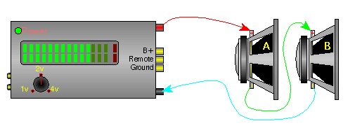
We described series speaker connections on a previous page. This page will explain how the impedance changes when speakers are connected in series. In a series connection you simply connect the positive terminal of speaker 'A' to positive terminal of the amplifier. Then you connect the negative terminal of speaker 'A' to the positive terminal of speaker 'B'. Lastly connect the negative terminal of speaker 'B' to the negative terminal of the amplifier. If both of the speakers have an impedance of 4 ohms, the total impedance will be 8 ohms. In a series connection, you simply add the individual impedances. If there were three 4 ohm speakers in series, the total impedance will be 12 ohms.


Parallel Connection:
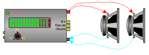
The impedance change with a parallel speaker connection is only slightly more complicated than the series connection. When speakers are connected in parallel, the impedance is reduced. This means that, given the same output voltage, the current demand on the amplifier will be increased. If all speakers have the same impedance, the total impedance is the impedance of a single speaker divided by the total number of speakers. If you have two 4 ohm speakers connected in parallel, the total impedance is 4/2 or 2 ohms. As you can see in the diagram below, all of the positive speaker connections are connected and then connected to the positive terminal of the amplifier. The same is done with all of the negative connections. You must be careful when paralleling speakers onto an amplifier. The impedance can quickly fall below safe levels. This is especially true when connecting speakers in parallel onto a bridged amplifier.


Enter the impedance of the speakers that are connected in parallel (starting at the top).
Data Input:
Speaker one's impedance? = ohms
Speaker two's impedance? = ohms
Speaker three's impedance? = ohms
Speaker four's impedance? = ohms
Data Output:
Two speaker's parallel impedance = ohms
Three speaker's parallel impedance = ohms
Four speaker's parallel impedance = ohms


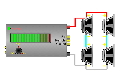
This is a series/parallel connection (below). Connecting individual woofers in a series configuration is not common in car audio. This is a lot more common in musical instrument (guitar and bass guitar) speaker cabinets.

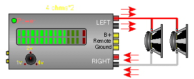
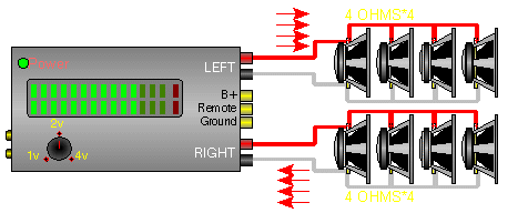
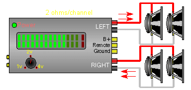
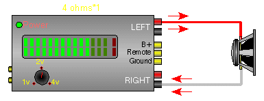
In the diagrams below, you can see the relative current flow from the amplifier's outputs (indicated by the red arrows) into various loads. At the bottom, you can see that 2 ohm mono (two 4 ohm speakers bridged) is the same as 1 ohm stereo (four 4 ohm speakers per channel).
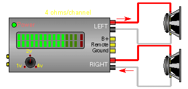
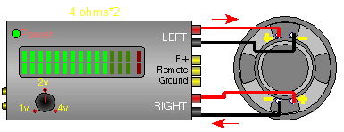
The image below shows the DVC speaker wired to both channels of a stereo amplifier. Each channel of the amplifier drives a 4 ohm load.

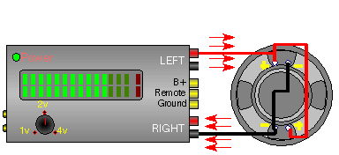
This image shows the DVC driver with both voice coils wired in parallel. This presents a 2 ohm mono load to the amplifier which may damage most amplifiers.
Impedance of each voice coil?
Actual Mono load:
Equivalent Ohms/Channel:


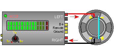
This image shows the two 4 ohm voice coils wired in series. This will present a 8 ohm mono load to the amplifier.
Impedance of each voice coil?
Actual Mono load:
Equivalent Ohms/Channel:


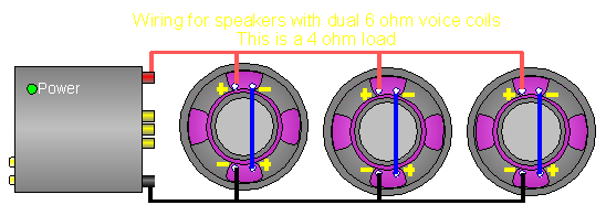
This diagram shows 3 DVC woofers with dual 6 ohm voice coils. The coils of each speaker are wired in series (which makes each speaker a 12 ohm speaker) and then all of the drivers are wired in parallel for a total of a 4 ohm load.
Impedance of each voice coil?
Actual Mono load:
Equivalent Ohms/Channel:


This diagram shows 2 DVC woofers with dual 2 ohm voice coils. The coils of each speaker are wired in parallel (which makes each speaker a 1 ohm speaker) and then all of the drivers are wired in parallel for a total of a .5 ohm load. You can calculate for more speakers by changing the input.
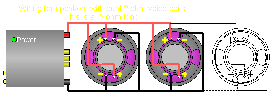
Impedance of each voice coil?
Number of Speakers?
Actual Mono load:


This is the wiring diagram for woofers with dual 4 ohm voice coils. This will give you a 4 ohm load. The voice coils of each individual speakers are wired in series. This gives each speaker an 8 ohm impedance. Wiring them in parallel will present the amp with a 4 ohm load.
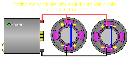
Impedance of each voice coil?
Actual Mono load:
Equivalent Ohms/Channel:


This is the wiring diagram for woofers with dual 2 ohm voice coils. This will give you a 2 ohm load. The voice coils of each individual speakers are wired in series. This gives each speaker an 4 ohm impedance. Wiring them in parallel will present the amp with a 2 ohm load. You can calculate for more speakers by entering the number of speakers in the correct field.
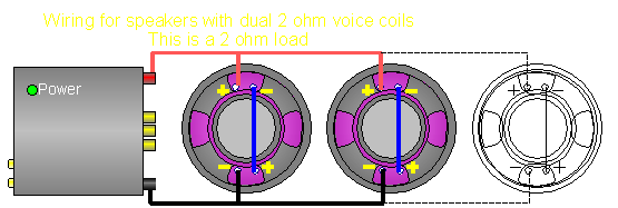
Impedance of each voice coil?
Number of Speakers?
Actual Mono load:


This diagram is a wiring diagram for 3 DVC drivers with dual 6 ohm coils. All of the voice coils are wired in parallel for a 1 ohm load. Class D and high current class AB amplifiers are probably the only amplifiers that can handle this load. Make sure that your amplifier can handle this load if you use this wiring configuration.
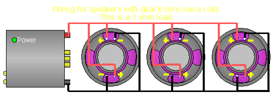
Impedance of each voice coil?
Actual Mono load:
Equivalent Ohms/Channel:


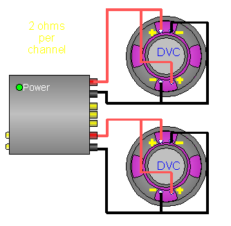
This diagram shows 2 DVC speakers with the voice coils wired in parallel. Each voice coil has an impedance of 4 ohms which results in a 2 ohm impedance for each speaker. One speaker is connected to each channel of the amplifier. This is a 2 ohm stereo load.
Impedance of each voice coil?
Equivalent Mono load:
Actual Ohms/Channel:

----- Critically Important -----
  • Flash graphics viewing/use alternatives:
  • Flash support by most modern browsers has been dropped but that's not the end of the line for Flash.
    There is no practical alternative to Flash for the interactive demos/applets/graphics on this site.. Especially when there are alternatives, some simple, some good, some...
  • Ruffle is chosen by most because they can't imagine using anything but their preferred browser. It works. It's OK but not great. The Flash graphics won't look as they're supposed to but it, generally, works.
  • The #1 preferred (my me) way to view the site and the Flash graphics is with the Chromium Portable browser and the installation of the older (no time-out) Flash Player files. This was incredibly simple when people knew computers but not today when people only know how to work with their phones.
  • The Flash Browser is a good option but it's so stripped down that it makes it somewhat difficult to use.
  • The Maxthon browsers are an option. The v4.95 is the easiest (install and use). V5.3.8 and 6.1.0 require (very) slightly more effort (very).
  • All of these browsers are available from my Flash Information page.
  • The Chromium and Maxthon browsers on the page above are 'portable' browsers. They are not installed into your system. They are simply made available for use on your computer. They can be carried around on a Flash drive and used on any computer.
----- Critically Important -----

For those who don't quite understand why too many speakers will damage an amplifier, maybe this will help.

OK, let's say that we have a water pump which is powered by an electric motor. This pump is designed to do whatever is necessary to keep the pressure constant (within the green range on the gauge). It is also designed to operate with a maximum of only two valves open at a time. In this first diagram, you can see that one valve is open and the RPMs are easily in the green. This is like a 2 ohm stable amplifier with a 4 ohm load. The motor RPMs are low and the system isn't stressed.

In this next diagram, you can see that there are 2 valves open and the RPMs are higher but still not in the red. It would likely run like this forever without a problem. This would be analogous to a 2 ohm stable amp with two 4 ohm speakers connected in parallel for a 2 ohm total load.

The diagram below shows how an amp might 'feel' with three 4 ohm speakers (for a 1.33 ohm load) on a 2 ohm stable amp. As you can see, the motor would have to be slightly in the red in an attempt keep up the proper pressure with three valves open. This is bordering on failure. When an amp is connected to a load that's below it's lowest rated load, something similar happens. Since more current is flowing than it should, the power supply can't keep up with demand and the rail voltage drops a bit. The excessive current stresses the output transistors and causes them to overheat. Compare this to the stress on the output pipe where it bends. When excessive demand causes excessive force to be applied to the bend in the pipe, the pipe could blow out (it's very thin pipe). Like the transistors in an amplifier, the absolute bare minimum was used to make it work as designed. When more is asked of it, failure is all but certain. Bear in mind that it doesn't matter if you didn't know that you were connecting the speakers the wrong way or not, a dead amp is a dead amp. You must know what you're doing.

This diagram shows all 4 valves open. The motor has to be pushed far beyond what it was designed for when pushed into redline to maintain pressure. It would be likely to fail prematurely. This is how a 2 ohm stable amplifier 'sees' a 1 ohm stereo or a 2 ohm mono load. It may seem like you know more than others when you run your amp into loads that are below the minimum suggested by the manufacturer but it's a bad idea and will lead to premature failure of your amplifier. Typical amp repairs now cost between $100 and $500, depending on the amplifier and the amount of damage. Many of the budget amps are not worth repairing unless you can repair them yourself and some are damaged so badly that they cannot be repaired.


Calculating Series and Parallel Resistance

Calculating Series Resistance:
Calculating series resistance is as simple as it gets. All you do is add the resistance of the individual components. If you have two 4 ohm speakers in series...


Total resistance = R1 + R2 +R3...
Total resistance = 4 + 4
Total resistance = 8 ohms for 2 series connected 4 ohm speakers.

Calculating Parallel Resistance:
Calculating parallel resistance is a little more involved but still fairly easy. There are 3 methods.

Method #1:
If all of the resistances are equal (all 4 ohm speakers or all 8 ohm speakers...), simply divide the impedance of a single speaker by the total number of speakers.


Total resistance = 4/2 (4 ohms speakers divided by the number of speakers)
Total resistance = 2

Method #2:
This one says that the sum of the reciprocal of the individual resistances is equal to the reciprocal of the total impedance. Well, I know that that sounds complicated but look at the following formula and you'll see that it ain't so bad. Let's do the calculations for two 4 ohm speakers in parallel.


1/(total resistance) = (1/R1) + (1/R2) + (1/R3)...
1/(total resistance) = 1/4 + 1/4
1/(total resistance) = .25 + .25
1/(total resistance) = .5
Total resistance = 2 ohms

Method #3:
This method is most useful for calculating the parallel resistance of 2 components. It can be used for more than two components at a time but the formula becomes convoluted and much more difficult. This method uses the product of the individual resistances divided by the sum of the resistances. Like this...


Total resistance = (R1*R2)/(R1+R2)
Total resistance = (4*4)/(4+4)
Total resistance = 16/8
Total resistance = 2

As you can see, all 3 methods result in the same answer.


Calculating Series/Parallel Resistance

Calculating the total resistance of a combination series/parallel network has to be taken in steps. If you have the following circuit with 2 parallel components in series with a third resistive component (we're going to consider the 4 ohm speaker to be purely resistive), first you have to calculate the total resistance of the parallel section. Then the total resistance is equal to the series component plus the total of the parallel components.
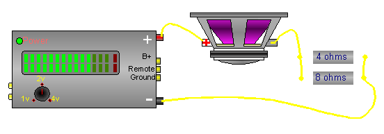
Parallel components:

Total parallel resistance = (R1*R2)/(R1+R2)
Total parallel resistance = (4*8)/(4+8)
Total parallel resistance = 32/12
Total parallel resistance = 2.67 ohms

Total parallel plus Series:

Total resistance = R1 + R2
Total resistance = 4 + 2.67
Total resistance = 6.67 ohms total


Click HERE to make this calculator fill this window.


You should remember:
1.In a series circuit, the current flow decreases and the impedance increases.
2.In a parallel circuit, the current flow increases and the impedance decreases.


Click HERE to visit a friend's new car audio tech site.


backward

forward


calculator