|
Balanced Line Drivers
Overview:
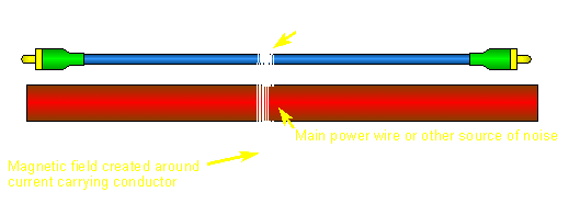
When audio is transferred from one audio component to another by electrical cables (not fiber optic cable), sometimes the cable will act as a lossy transformer and pick up some of the noise in the vehicle. This problem becomes worse when the electrical 'environment' is especially noisy or the cable length is really long. A balanced line driver takes an unbalanced signal and converts it to a balanced signal. The balanced signal makes it easier to cancel out the noise, leaving a 'clean' signal. If you run your preamp cables next to your power wire (like the diagram below), you're more likely to pick up noise with an unbalanced signal line than with a balanced signal line.

Signal Types
Unbalanced Signal:
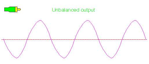
In the diagram below, you can see that the center conductor has a signal (a sine wave in this case) on it and the shield is connected to ground (which means it has no signal on it).

Balanced Signal:
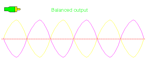
A balanced signal will have, in virtually all cases, signals that are the same in all respects except for the fact that one is a mirror image of the other. In the diagram below, you can see that the center conductor AND the outer shield have signals on them. These signals originate from identical drive circuits (they'll have the same output impedance and drive capabilities). There is also a third connection which is usually connected to ground. If the line driver uses RCA type connectors the ground connection is the chassis/power ground. If the connector is a mini DIN connector, the cable's shield is the ground conductor. Other types of connectors will have dedicated ground connections.

Unbalanced to Balanced Signal:
In the diagram below, you can see that the line driver takes in an unbalanced signal and converts it to a balanced signal. It actually takes the input signal, inverts it and applies the inverted signal to the shield conductor.

Line Driver and Receiver:
Some line drivers are designed to be used with a dedicated receiver. The balanced line receiver is necessary when the next device in the audio chain can not handle a balanced input signal. The balanced line receiver will simply convert the balanced signal into an unbalanced signal. The following diagram shows the signal as it pass from one component to the next. You can see that the signal starts off unbalanced. Then it's converted to a balanced signal by the line driver. And finally it's converted back into an unbalanced signal by the receiver. If there's a gain/level control on the driver there will likely be gain/level controls on the receiver.

Doubled Output Voltage:
In this diagram, as with all noise canceling inputs used in car audio, the line driver's input signal is the difference of potential (voltage) between the center conductor and the shield. This voltage is the difference of potential between any point on the sine wave and the reference. At the white line, this would be the instantaneous voltages labeled point A and point B. This input signal is the same signal that your amplifier would receive without the line driver. At the line driver's output, you can see that the difference of potential between points C and D is twice the difference of potential between points A and B. This translates into a 6dB increase in the signal level. This will allow you to reduce the gain settings on your amplifier or other signal processors which will effectively increase the system's S/N ratio by 6dB.

Noise Rejection:
One benefit of the balanced line system is an ability to reject noise which may be induced into the audio signal path between two audio components. Earlier we said that an audio device uses the difference of potential between the shield and the center conductor as the audio signal (with RCA type connectors). With an unbalanced signal the shield is grounded and is unlikely to pick up noise along the signal line because it has a very low output impedance (large conductor connected to ground). The center conductor, however, is not grounded and is more likely to pick up noise (it's output impedance may be as low as 50 ohms or as high as 600 ohms). If the audio signal is considered to be the difference between the voltages on the shield and the center conductor and the noise is only induced into the center conductor, the induced noise will become part of the signal. In a balanced signal system, the noise would be induced into the center conductor's and the shield's signal equally but the noise is canceled out because the noise is on both of the signal lines and the signal used by the amplifier (or balanced receiver) is the difference between the two signal lines. If the noise has a magnitude of 1.5 volts, the amplifier 'sees' 1.5 volts minus 1.5 volts which is 0 volts (if I'm not mistaken).
In the following drawing you can see a 100hz sine wave mixed with a 5khz sine wave. The 5khz tone simulates 'engine noise'. You can also see how the engine noise is in phase on both signal lines (look at the dashed vertical line for a reference) while the audio signal is 180º out of phase (inverted).

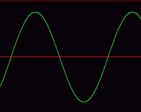
When the amplifier or balanced line receiver receives the signal, it will subtract the two signals from one another. This means that the engine noise will cancel itself out while the 100hz part of the signals will double. This is the resultant output.

Head Units with Balanced Outputs:
The output of the balanced line driver is a balanced signal. Some head units also have a balanced output signal. I added this section for those who may want a little more information specifically related to head units. The diagram below shows the signal output configuration of a head unit with unbalanced outputs. The signal is on the center terminal of the RCA cable and the shield is connected to the chassis ground of the head unit.

This diagram shows a balanced output signal. As before, the center conductor has one signal and the shield conductor has an inverted version of the center conductor's signal. This type of output is capable of producing twice the effective output voltage of the unbalanced configuration. The heads that say they can either produce 4 volts unbalanced or 8 volts balanced have these 2 types of outputs. They can be selected by either a switch or they may have different sets of RCAs for the 2 types of outputs.

|


