The terms 'regulated' and 'unregulated' refer to the power supply control circuits.
UNregulated Power Supply:
An unregulated power supply is by far the simplest switch mode power supply (SMPS) used in mobile power amplifiers. The transistor(s) driving each half of the transformer primary winding are driven at full duty cycle. The duty cycle does not change during normal operation. No matter how low or high the battery voltage gets, the duty cycle will not change. Unless, of course, the voltage gets too low to operate. Then the supply control chip will simply quit driving the power supply FETs (the supply will shut down completely). Under normal operating conditions, the no-load rail voltage (amp idling, no audio out) will vary in direct proportion to the battery voltage.
Unregulated Power supplies and Changes in Battery Voltage:
As we mentioned above, the battery voltage is not constant. It may vary from 11.5-12.5 volts with the engine off to ~14.4 volts with the engine running. If the battery voltage is 12 volts and the transformer has a 1:2 ratio as in the previous example, the power supply will produce ±24 volts. If the battery voltage is 14.4 volts, the supply will produce ±28.8 volts (an extra 9.6 volts). This is why amplifiers with unregulated power supplies have significantly different power ratings with different battery voltages. A change in battery voltage directly effects the rail voltage. If the output transistors were 100% efficient (they aren't) and could deliver the full rail voltage to the speakers, the following calculations show you how the difference in battery voltage produces different power outputs into a 4 ohm speaker load.
Using the formula:
P = E2/R
At 12 volts...
P = 242/4
P = 576/4
P = 144 Watts (peak power)
At 14.4 volts...
P = 28.82/4
P = ~207 Watts (peak power)
As you can see, there is a significant difference in power output with the 2 battery voltages.
----- Critically Important -----
Adobe has deemed that the Flash content on web pages is too risky to be used by the general internet user. For virtually all modern browsers, support for Flash was eliminated on 1-1-2021. This means that those browsers will not display any of the interactive Flash demos/calculators/graphics on this (or any other) site.
The simplest (not the best) fix, for now, is to download the Ruffle extension for your browser. It will render the Flash files where they were previously blocked. In some browsers, you will have to click on the big 'play' button to make the Flash applets/graphics visible.
An alternative to Ruffle for viewing Flash content is to use an alternative browser like the older, portable version of Chrome (chromium), an older version of Safari for Windows or one of several other browsers. More information on Flash capable browsers can be found HERE. It's not quite as simple as Ruffle but anyone even moderately familiar with the Windows Control Panel and installation of software can use Flash as it was intended.
Stiffly regulated power supplies
In an unregulated power supply, the engineers simply use the transformer ratio along with the primary voltage to determine the rail voltage but battery voltage fluctuations (and copper and core losses) cause the secondary rail voltage to fluctuate. In a stiffly regulated power supply, there is a circuit which continually monitors the rail voltage and varies the duty cycle to keep the rail voltage very close or exactly at the target voltage. At no point in time, under normal operating conditions, will the rail voltage fall below the target voltage.
The following demo shows the duty cycle for both a stiffly regulated supply and an unregulated supply under varying conditions.
If, in a regulated power supply, we want a total secondary target voltage of 48 volts (±24 volts) with a 12 volt battery voltage (as in the first example) we could use a 1:2 ratio but as soon as a load is placed on the power supply rails (because you turned up the volume), the rail voltage sags, even if the power supply pushes the FET duty cycle drive to 50% (as high as it can go). Why? The transformer doesn't have enough ratio to overcome losses (due to inefficiencies). If we increase the ratio to 1:3, the control chip in a regulated power supply will reduce the duty cycle to prevent overshooting the target voltage (when there is little or no audio output). Now, when current is drawn from the power supply rails, the duty cycle is increased just enough to maintain the target voltage. In a stiffly regulated power supply, the transformer ratio may be 50 or 60 percent higher than in a non regulated power supply. An amplifier with a stiffly regulated power supply can typically double the power output when the impedance is halved (4 ohms to 2 ohms per channel for example). The tradeoff (and there are always tradeoffs in any type of design) with stiffly regulated supplies is a somewhat lower efficiency and a reduction of power output with lighter loads (Stay tuned, I'll explain in the next section). If you remember the Ohm's law formula for power P=E^2/R, you can see that the power output will double if the resistance is cut in half when the voltage applied across the speaker load remains constant (regulated, in this case). This type of power supply can generally maintain its rated power output over a large range of battery voltages.
One Drawback of Tight Regulation:
From the previous example, remember that the ratio was 1:3 but the target voltage was only 48 volts (±24 volts). If the power supply with the 1:3 transformer was allowed to drive the FETs at a full 50% duty cycle, as in the unregulated power supply, the no load rail voltage would be 72 volts (±36 volts). This means that the amplifier has the capability to produce higher rail voltage and therefore more power output into light (4 ohm stereo) loads but is limited by regulation. Some manufacturers use the stiffly regulated power supply so that they can say that the amplifiers can double their rated output by reducing the impedance by half (this is considered to be a big deal by some consumers). Others may use a regulated supply because some components are sensitive to high voltage and they are being run close to their maximum safe operating levels. This, for example, happens when an engineer is trying to maximize capacitance with limited space (higher voltage capacitors with the same capacitance would be physically larger). The stiff regulation also makes it easier to maintain proper biasing of the output transistors which may (but not necessarily) mean better sound quality at low volume.
Moderately-regulated power supply:
MANY amplifiers fall into this category. This, in my opinion, is the best of both worlds. This type of power supply uses a transformer ratio slightly higher than that needed to produce its target voltage. It's duty cycle (typically) is less than 50% when the battery voltage is greater than 12 volts (actual voltage determined by the circuit designer) and/or there is very little current flowing from the rails (when the amp is at idle). As soon as the rail voltage falls below the target voltage, the duty cycle quickly goes to ~50% (full duty cycle). This type of power supply will prevent an overvoltage condition on the secondary of the power supply and is also very efficient.
In any type of design, there are always tradeoffs, There is no 'best' design. Some are good in one respect but are less than perfect in other respects.
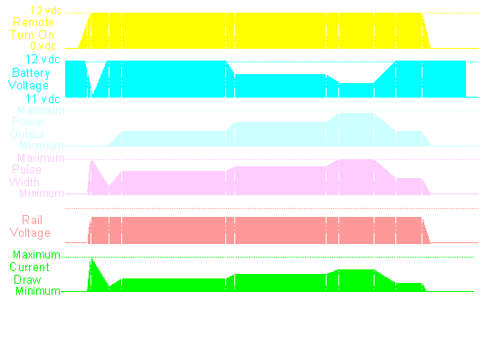
Power Supply Timing Chart:
The following diagram is a timing chart and is one of the best tools to show how multiple things relate to one-another. This chart shows how various parts of an amplifier with a regulated power supply relate to each other.
At this point, you can see that the remote is switched on and the amplifier 'comes to life'.
At point B, you can see a few things happen:
The current draw peaks as the amplifier charges the rail capacitors.
The battery voltage drops during the current surge. You might notice your lights in your car dim when you turn your amplifiers on.
The rail voltage goes from minimum to maximum. Remember that this is a regulated power supply.
The pulse width goes from minimum to maximum. This is because the amplifier is doing its best to get the rail voltage to its target voltage as quickly as possible.
At this point you can see:
The current draw goes back down as the rail caps are now charged.
The battery voltage stabilizes because the amp is pulling less current.
The rail voltage has stabilized.
The pulse width goes back towards minimum because the rail voltage is at its target voltage.
At point D, an audio signal starts to play and...
The current draw increases slightly as the amplifier drives the speakers.
The pulse width increases slightly to keep the rail voltage at its target voltage.
At this point, the power output starts to increase and...
The pulse width starts to ramp up.
The current draw starts to increase.
At point F' the audio output levels off and so do the pulse width and the current draw
At this point, the power output, again, starts to increase and...
The pulse width starts to ramp up to maintain rail voltage.
The current draw increases until the current demand levels off.
At this point, all demand has levelled off. You should notice how the battery voltage dropped when current demand increased. If the alternator was charging, the voltage wouldn't drop (except for the short period of time it takes for the voltage regulator to react).
As the audio output starts to fall (the volume of the test tone is reduced)...
The battery voltage starts to recover.
The pulse width starts decrease.
The current draw starts to decrease.
At point J, everything levels off.
The amplifier's remote power source is switched off and...
The power supply shuts down by reducing the pulse width to nothing.
The rail voltage falls because the switching power supply is no longer operating.
The audio is muted and reduced to silence. Even if there were no muting circuit, the audio would still be reduced to nothing because there is no rail voltage.
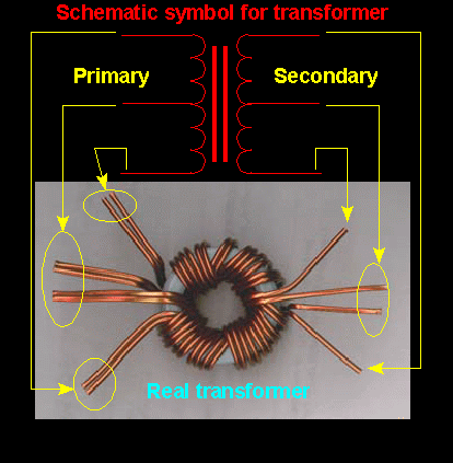
The diagram below shows the relation between the parts of the schematic diagram symbol and a real life transformer. Note the double primary windings. These are used to handle higher current without overheating.
This site was started for pages/information that didn't fit well on my other sites. It includes topics from backing up computer files to small engine repair to 3D graphics software to basic information on diabetes.
This site introduces you to macro photography. Macro photography is nothing more than the photography of small objects. It can take quite a while to understand the limitations associated with this type of photography. Without help, people will struggle to get good images. Understanding what's possible and what's not possible makes the task much easier. If you need to photograph relatively small objects (6" in height/width down to a few thousandths of an inch), this site will help.
If you're interested in air rifles, this site will introduce you to the types of rifles available and many of the things you'll need to know to shoot accurately. It also touches on field target competition. There are links to some of the better sites and forums as well as a collection of interactive demos.
This site helps anyone new to computers and anyone with a basic understanding of computers with a desire to learn more about the internal components of a computer. If you have a computer that you'd like to upgrade but don't know where to start, this is a good site for you.
This site is for those who want to begin racing karts but don't fully understand how the various parts work. It's mostly interactive demos that show how the various parts of the kart work.
Click HERE to visit a friend's new car audio tech site.