Email   Home Page


Amplifier Gain Controls

Contrary to popular belief, an amplifiers gain control does not determine the maximum power that an amplifier can produce. As long as the preamp/drive signal has sufficient level, the amplifier will produce its maximum power output level. The gain controls are used to match the amplifer's gain to the gain of the other amplifiers in the system (in the case of a multi-amp system). The gain controls also allow you to match the amplifier(s) to the head unit. Not all head units have the same maximum preamp output voltage. Some head units are capable of producing 9 vrms out while others are only capable of 1.5 vrms out.

Please note that a head unit will reach its maximum output level (clipping) well before the volume control reaches the upper end of its range (usually at a point of 85-90% of its maximum range). This is especially true of tape decks, not because the audio section is of lesser quality but because some tapes are recorded at lower levels than others and the manufacturer must design the deck to be able to produce a sufficient output level with virtually any tape.

  • Note:
  • This example uses a rotary volume control instead of the digital type pushbutton controls but the same basic concept applies.
  • The output of some decks will clip at less than 50% of its full volume when the loudness is engaged or bass and treble are boosted. Many of the low to mid priced head units have a maximum output level (before clipping) of 2 vrms. If a 100hz test tone is played in the head unit and the bass control boosts signal levels at 100hz by 10dB, the output would clip if the pre bass boosted signal would have been .63 vrms. In other words, If the output of the 100hz test tone is more than .63 vrms and the bass control was turned to its maximum level, the signal would clip. This would very likely be at less than one-half volume.


Note:
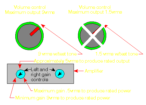
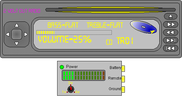
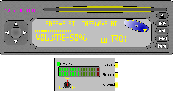
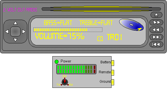
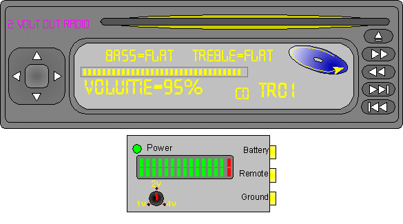
The red arrows (near the volume controls) in the following drawings are showing you the position of the volume control which will produce the maximum (without clipping) output voltage. The test signal would be a tone recorded at its maximum level. This first section principally applies to tape decks.

The diagram below shows the approximate position of the volume control which will drive the amplifier to reach its rated power. Notice that the gain controls are set at 5vrms. The head that only produces 1.5vrms cannot drive the amplifier to rated power. The head unit rated for 9vrms drives the amplifier to its rated power with its volume control at approximately the '10 o'clock' position (which will make it difficult to adjust the volume precisely). This would not be an acceptable gain setting for either head unit.
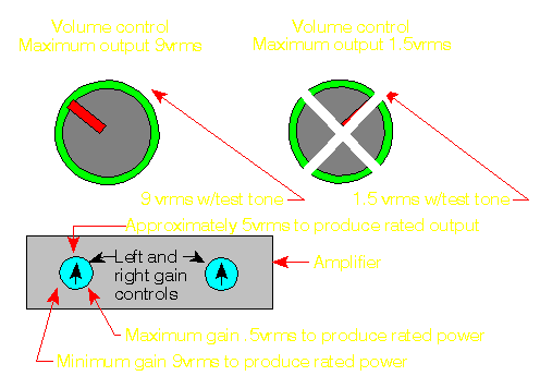

This diagram shows the gain control set to 9vrms. The head unit capable of producing 9vrms would be able to drive the amplifier to its rated power. The 1.5 volt head unit would not be able to drive the amplifier to its rated power. This would be a good setting for the 9vrms unit but would NOT be good for the 1.5vrms unit.

This diagram shows the gain control set to 1.5 volts. At this gain position, the 9vrms head unit will drive the amp to rated power at a very low volume control position. The 1.5vrms head unit can drive the amplifier to rated power and would be an acceptable gain position for the 1.5 volt head unit.
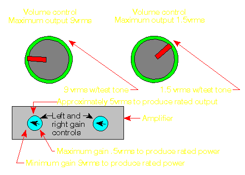
As you can see, the gain controls match the head unit to the amplifier. No single gain position is right for every head unit. There are many factors which must be taken into account when setting the gain controls in any audio system. Setting the gain controls so that the amplifiers were never driven into clipping with the 0dBfs 100hz test tone would likely leave you with a system which would not produce sufficient output with a typical music source. The previous example is only to show you the relationship between the head unit output and the amplifiers gain controls.


Note:
This demo assumes that the test signal is a sine wave recorded at the highest level possible (0dBfs). It also assumes that all tone controls are set flat and the loudness coutour is switched off.

This is essentially how a system should be set up. The head unit should be able to use most of its range before the amplifier is driven into clipping. Again, if the gains are set too low, the head unit won't be able to drive the amplifier to its maximum output level. If the gains are set too high, the amp will be driven into clipping at a very low volume level (on the head unit).

Clarification of Terminology:
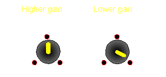
Generally, when someone says that you need to 'turn the gains up', you need to make the amplifier more sensitive. When you make the amplifier more sensitive, it will take less input signal to to produce a given amount of power. The confusion comes in when you look at the gain control markings on the amplifier. If they are marked in volts, it's generally the amount of input voltage that it takes to produce full power. When you turn the gains 'up' you turn the gain control to a 'lower' (smaller) number. For example, the gains are higher at 2 volts than they are at 4 volts.


And to show it in another way...
At the risk of being redundant, the following diagram shows how the output of the amp relates to the output of the amp at different gain settings.


  • This calculator will show you how the gain settings control the output of the amplifier.
  • You may manually enter the gain setting, input voltage and speaker load.
  • This is based on a hypothetical 100 watt/channel amplifier.
  • The gain setting is the amount of input voltage which will cause the amplifier to reach maximum power.
  • Notice the signal status indicator
  • Notice how much quicker the power goes toward clipping when the gain value is set at lower values. Remember that the gain tells you how much input voltage will cause the output to be driven to clipping.
Data Input:
Gain setting? Volts
Speaker Load? Ohms
RCA Input? Volts
Data Output:
Output = Volts
Output = Watts
Signal Status:  


This is another gain control calculator. It's fairly self-explanatory. One note... If the tops and bottoms of the amplifier sine waves go out of view, the amp is clipping. The right negative is inverted because the amplifier is bridgeable (as are most amplifiers on the market) and the signal output is on the right negative. The bridging terminals for many amplifiers are the left positive and right negative.

----- Critically Important -----
  • Flash graphics viewing/use alternatives:
  • Flash support by most modern browsers has been dropped but that's not the end of the line for Flash.
    There is no practical alternative to Flash for the interactive demos/applets/graphics on this site.. Especially when there are alternatives, some simple, some good, some...
  • Ruffle is chosen by most because they can't imagine using anything but their preferred browser. It works. It's OK but not great. The Flash graphics won't look as they're supposed to but it, generally, works.
  • The #1 preferred (by me) way to view the site and the Flash graphics is with the Chromium Portable browser and the installation of the older (no time-out) Flash Player files. This was incredibly simple when people knew computers but not today when people only know how to work with their phones.
  • The Flash Browser is a good option but it's so stripped down that it makes it somewhat difficult to use.
  • The Maxthon browsers are an option. The v4.95 is the easiest (install and use). V5.3.8 and 6.1.0 require (very) slightly more effort (very).
  • All of these browsers are available from my Flash Information page.
  • The Chromium and Maxthon browsers on the page above are 'portable' browsers. They are not installed into your system. They are simply made available for use on your computer. They can be carried around on a Flash drive and used on any computer.
----- Critically Important -----


Click HERE to make this applet fill this window.


You May Be Interested in My Other Sites

You should remember:
1.The gain controls are designed to match the amplifier to the head unit.
2.The gain controls do NOT determine how much power an amp will produce.


Click HERE to visit a friend's new car audio tech site.

backward

forward


calculator