
|
| Email Home Page |
|
|

|
| Email Home Page |
|
|
|
There are several benefits of using electronic crossovers instead of passive crossovers. This page will cover the advantages and disadvantages of each type of crossover.
Setting Crossover Frequency:
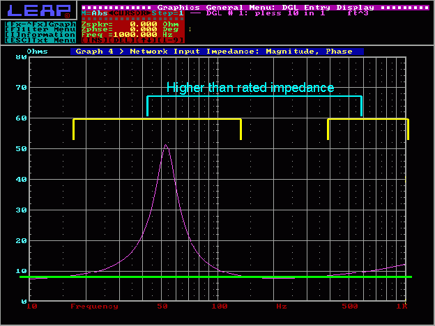
Changing the Crossover Frequency: On the following graph, you can see that the speaker's actual impedance (violet line) is significantly higher than its rated impedance (green line). The yellow brackets indicate the frequencies where the impedance is above the speaker's rated impedance. If you designed a passive crossover for the speaker's rated impedance and the crossover point fell anywhere in the yellow brackets, the crossover point would be shifted to another frequency.
Increased Headroom:
 And here you can see a 2000hz sine wave.
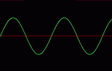
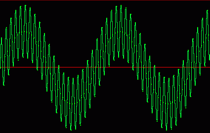
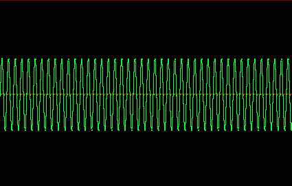 You can see (in the previous pictures) that neither of the sine waves are near the top or bottom of the window (black area). In the next picture you can see that the higher frequency is 'riding' on top of the lower frequency. When both of the frequencies are mixed together, you can see that they are very close to reaching the top and bottom of the window (we will consider the top/bottom borders of the window to be 'clipping'). You should also notice that the signals are exactly the same levels that they were before they were mixed. If the volume was only slightly increased, the amplifier would start to clip. When using an electronic crossover, the signal in the third picture is separated into the signal in the first and second pictures (if the crossover point was set approximately in the center of 100 and 2000hz).
 Actually, the signals would look more like the following pictures because the undesired part of the signal would not be 'entirely' removed. It would look more like the following two drawings. Of course, the crossover's actual output signal depends on the input signal, the crossover frequency and the slope of the crossover. If the crossover frequency was low pass and set closer to 100hz than 2000hz, the mixed signal would look more like the following drawing. You can see that the level of the 100 hertz part of the signal is the same as when it was produced alone. The 2000hz part of the signal is significantly reduced.
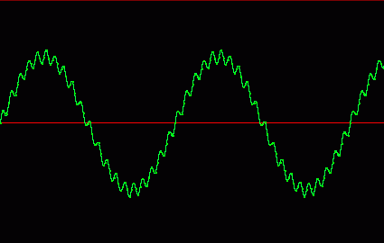
This is the mixed signal when run through a high pass crossover set at approximately 1000hz. You can still see that the 100hz signal is partially there but at a much reduced level.
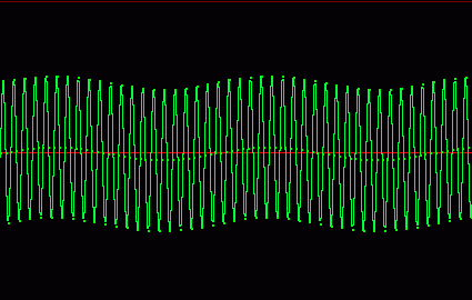 You can see that the signal has much more headroom after the unwanted part of the signal is removed. If you use a passive crossover, it will block the frequencies from getting to the speakers but you'll have reduced headroom because the signals are still mixed together.
Clipping and Passive Crossovers:
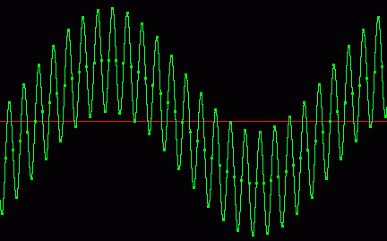
The following diagram shows how the signal clips if the level is increased by 20%. If we use a passive crossover, the low frequencies would be filtered from the signal going to the tweeter but the signal would be distorted because the amp was driven into clipping.
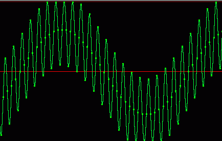
Again, the signal would look something like this if an electronic crossover was used and the lower frequencies were cut before the amplifier. You can see that the tops and bottoms of the high frequency waves are symmetrical. You should also note the significant amount of headroom that's left before the signal would be driven into clipping.

The following signal is what would get to the tweeter (through the passive crossover) if the amplifier was clipped because it had to amplify both the high and low frequency tones. Notice that the wave form is no longer symmetrical (some tops and some bottoms are shorter than they should be). This signal is distorted.
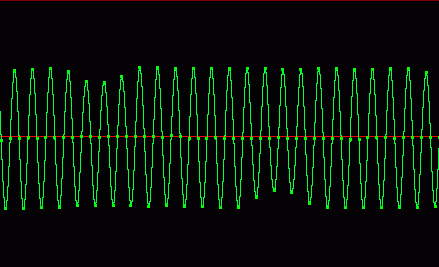 You can see that the added head room (increased because the lows were filtered from the signal before it got to the amp) allows the high frequency signal to be produced at higher levels because it's not 'riding' on top of the low frequency wave.
This page should not lead you to believe that passive crossovers are the completely useless. They can (and do) work very well but they do have some drawbacks (as shown above). They also have a few advantages such as not needing multiple amplifiers and... OK, maybe there's only one advantage. :-) |

|

|
|

|