|
The "Computer"
|
|
The "Computer": Front Panel Buttons/Switches:
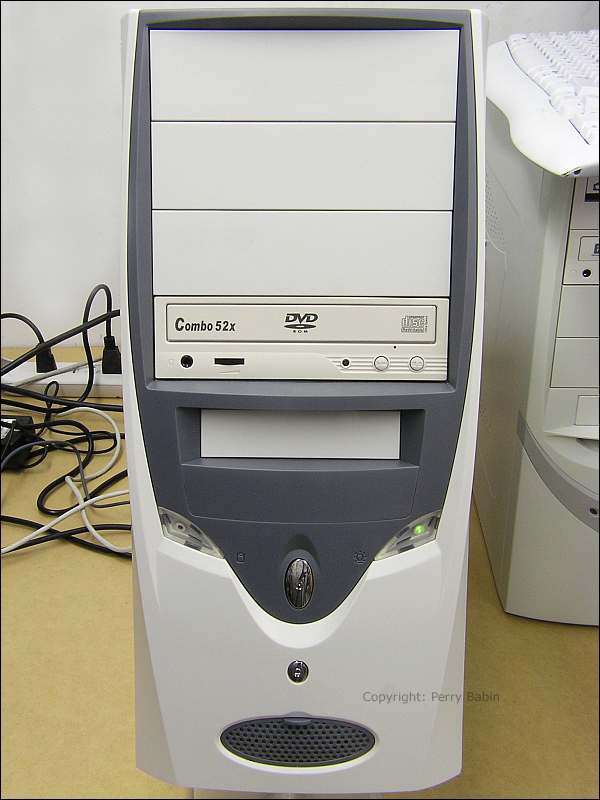 I mentioned the 'power' and 'reset' switches. On new computers, they have somewhat universal markings to indicate which is power and which is reset. In the following image, you can see the front of a computer (a different computer). The power button is marked with the 0/1. The reset switch (the same color as the case here) is marked with a triangle inside of a circle.
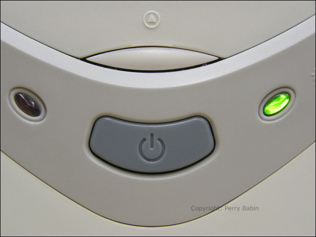 Front Panel Lights/Indicators: Rear Panel Switches:
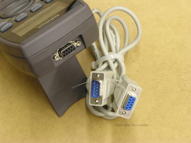
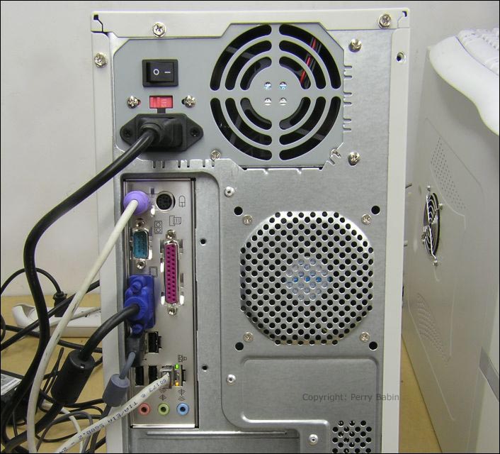 Rear Panel Connectors: * At the top of the connector panel (just below the power supply), you will see two connectors. One has a purple plug in it. The other is open. These are PS/2 ports and are used for the keyboard and mouse. Typically, they are color-coded to match the connectors but these are not. * Just below the PS/2 ports, you see a 9 pin d-sub connector. This connector (with 9 'pins' instead of tiny sockets as are found on the other d-sub ports) is a serial port. It's used for data transfer. In the past, it was used for the mouse. Now it's not used very often except for specialized communications. For example, I have a multimeter that plugs into that port and allows the computer to log data from the meter. Many new motherboards are not offering this connector. If you need to tell a piece of software that you want to to use this port for some function, you will tell it to use the 'COM' port. Below is the multimeter I mentioned and the serial data cable that is used to connect it to the computer.
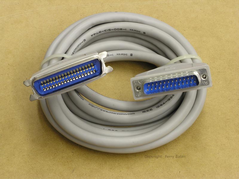
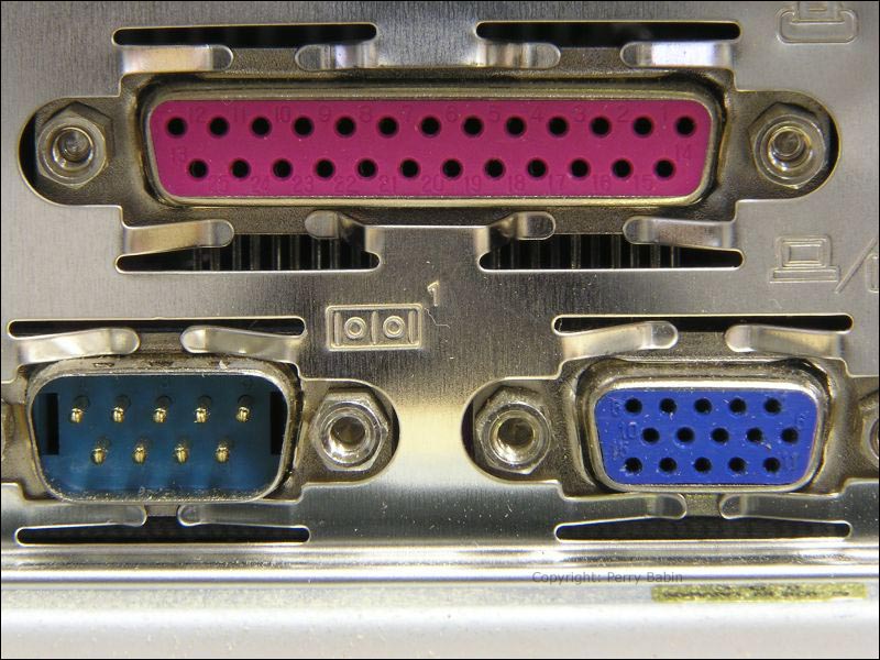
 * To the right of the serial port connector, you can see a 25 pin d-sub connector. This is a parallel port and it's typically used for older printers. If you have to tell a piece of software to use this port, you will have to tell it to use the LPT-1 port. Most newer printers use USB ports. These are also being phased out. Below, you can see a parallel printer cable. The computer end of the cable has a 25 pin d-sub connector. The printer end has a 36 contact Centronics connector.
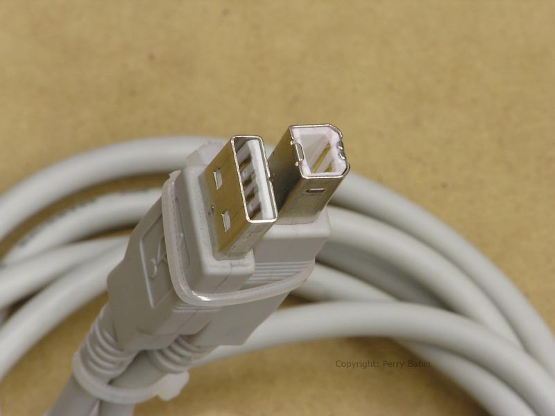
 * The next port (left and below the printer port) is the video port (VGA port). It uses a 15 pin d-sub connector. It's where you will plug in your video monitor. Keep in mind that there are significant differences between computers and not all will have a VGA port here (integrated into the motherboard). On some computers, you will have a dedicated graphics (video) card. The dedicated card typically offers much greater performance but can add significantly to the price of the computer. Some popular graphics cards (used by people who play high-end video games) cost more than the entire computer that's used in this tutorial. * Below the VGA port, you can see 4 rectangular ports (one has the mouse plugged into it -- black plug/gray cable). These are the current standard for interconnectivity. Most modern computers have at least 4 ports on the rear panel. Most motherboards have the option to have at least 2 more USB ports that are accessed on the front of the computer (if the case has front panel USB connectors). The following cable is used on most printers and scanners. It's a USB A/B cable. The 'A' end is the flat connector. The 'B' end is the one that's more square.
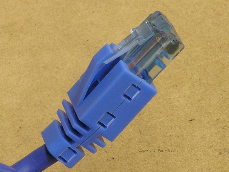
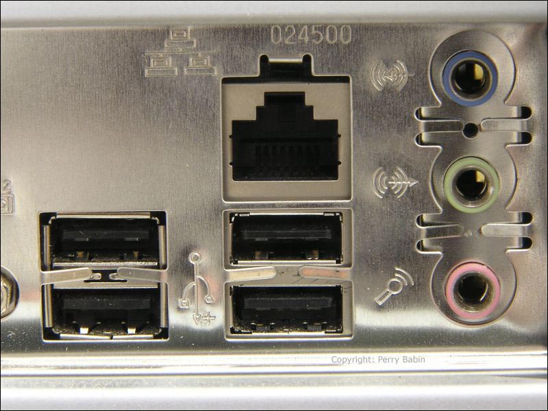
 * Just to the right of the lower USB ports, you will find the on-board LAN (Local Area Network) connector. It's an RJ-45 telephone type connector. The LAN allows you to connect to your DSL/cable modem, to the a router/switch or to another computer. One light indicates that the cable is connected to a working port (on the other end). The other light flashes when there is activity through the port. Sometimes, one of the lights will change color to indicate the LAN operating speed but this varies by manufacturer. The following image shows a LAN cable connector. Notice the little lever and the boot that covers the lever. The boot prevents the connector from snagging when you're pulling the cable out of a bundle of other cables.
 * The round connectors at the bottom of the panel are for audio. The connectors are color coded. By default on this machine, the green is the audio 'output' port. It's where you plug the connector for your speakers or headphones. The blue connector is for audio 'input'. The pink connector is the microphone input. This color coding is for standard '2 channel' audio output. For 6 channel audio (on a board without dedicated connectors for all 6 output channels), the pink and blue connectors double as the surround speaker output, center channel output and sub channel output. To set the blue and pink connectors to be used as outputs, you may have to go into the audio control panel to select the proper setting. A few cards make the change when they sense that you've plugged speakers into the blue and pink jacks but that feature is seldom seen (on the boards that I've used). You have to consult your motherboard's manual to determine what your board has. I'll cover more advanced sound cards later in the tutorial. The next 3 images show the back panel of a different computer. The first image shows color-coded PS/2 ports. These are for the mouse and keyboard. Newer computers don't have these. They use two of the USB ports for the mouse and keyboard.
 The image below shows all of the d-sub connectors. As you can see, there are little fingers between the metal panel and the connector housings. These assure that there is a good electrical connection between the motherboard's ground and the computer case. You will see similar fingers on all of the case panels. They insure that there is a good electrical connection between the case and the side panels. All of these extra electrical connections prevent leakage of high frequency noise. The noise would not be audible because it's well beyond the audible frequency spectrum (in the radio frequency range). If not contained, the noise would tend to interfere with signals such as video and transmitted radio signals.
 The following image shows the USB, LAN and audio connectors. You'll notice slight differences (such as no lights on the LAN port) but they're essentially the same as the previous computer's rear panel.
|
|
| Contact Me: babin_perry@yahoo.com | |
|
Perry Babin 2005 - Present All Rights Reserved
|