
|
| Email Home Page |
|
|

|
| Email Home Page |
|
|
|
There are many instances where the load that needs to be driven isn't compatible with the piece of equipment that's available to drive the load. This can be for audio or virtually anything that uses an AC waveform to transmit the signal/power/waveform. Impedance matching transformers make the load seem like the load that it was designed to drive.
Transformer Basics:
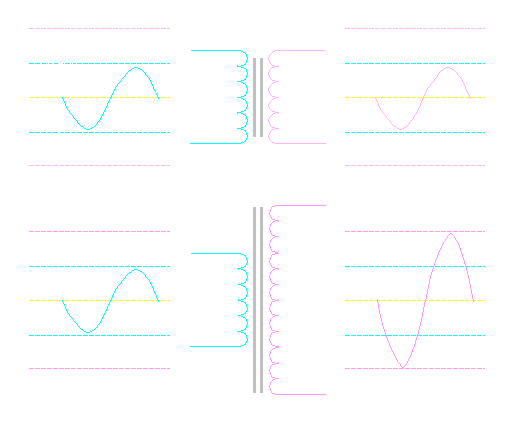
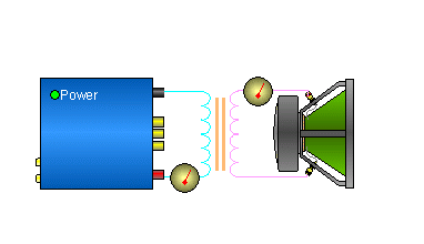
Power: For the next section, we will consider an amplifier that's capable of delivering 50 watts into a 2 ohm load. This means that it can deliver only 10 volts into the speaker load. It is also designed to deliver 5 amps into the speaker load at full power. The speaker we will use has an 8 ohm impedance. If we connect a 1:1 transformer to an 8 ohm speaker (as in the diagram below) and drive the primary with 10 volts, the transformer will transfer the voltage to the secondary and therefore to the speaker. If we use the formula P=E²/R We will see that the 10 volts will only be able to produce 12.5 watts.
Input-Output Power:
If we use the formula P=I*E to find the current flow through the windings.
Primary and Secondary Current:
The current flow through both windings of the 1:1 transformer is 1.25 amps.
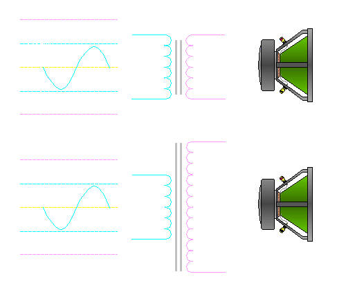
If we drive a 10 volt signal into a transformer with a 1:2 ratio and have the 8 ohm speaker connected to the secondary, the voltage across the 8 ohm speaker will be 20 volts. Remember that the voltage on the secondary is twice the primary voltage (because we have a 1:2 ratio). If the voltage is doubled and the load (8 ohms) stays constant, the current is doubled. This will allow the power driven into the 8 ohm speaker to be quadrupled. If we go back to the formula P=E²/R...
Secondary Power:
If the speaker is getting 50 watts of power and the transformer doesn't make any power, then that means the amplifier is producing 50 watts with an output of 10 volts. To do this, the amplifier will have to deliver more current at 10 volts. If we use the formula P=I*E, we can see that the current flowing from the amplifier is 5 amps.
Primary Current:
Primary Power: Remember that when we drove the speaker with 10 volt signal, we were only be able to deliver 12.5 watts into the speaker. With the transformer, the same amplifier could deliver 50 watts into the 8 ohm speaker. This is the same amount of power that the amplifier would be able to deliver into a 2 ohm speaker (which we didn't have).
Current/Voltage Ratios:
Mathematically...
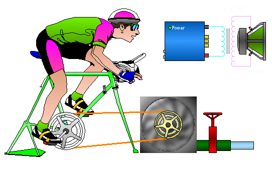
In the following graphic you can see that the pulley on the cycle and the pulley on the pump are the same size. This would allow an average rider to keep up with required demand for pumped water. The speed at which the pedals must be driven around and the torque that must be applied to the pedals would allow an average rider to drive the pump at the required rate. A smaller rider might be able to pedal fast enough but the ratio of the primary pulley (driven on the cycle) to the secondary pulley (on the pump) would make it impossible for him (or her) to pump the required amount of water (he or she would not have enough strength to develop the torque to drive the pump sufficiently with this pulley combination). A larger (body builder type) rider might easily be able to push the pedals around but might not be able to keep up with the speed that 's required to pump a sufficient amount of water. Again... this would be a good set-up for an average rider. This is analogous to an amplifier designed to produce full power into a 2 ohm load driving a 2 ohm speaker through a 1:1 transformer. Think of the silver pulley as the primary (driven) winding of the transformer and the gold pulley as the secondary winding. The orange belt is the magnetic field connecting the primary to the secondary.
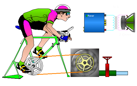
The set-up below would be best suited to the smaller quicker rider. This ratio would require less torque but more pedal speed to pump the water at the required rate. An average rider may be able to pump enough water but it's not optimum for him. The body builder would not likely be able to produce enough pedal speed with this combination. The amplifier (that's optimized for 2 ohm loads) would be able to drive it's rated power into a 1.5 ohm speaker load if the transformer ratio is 1.33:1. If we equate torque to current and equate pedal speed to voltage and remember that power into the transformer is equal to power out of the transformer (ignoring losses) we can see the following. The voltage is going to be higher on the side of the transformer with the most windings (he primary in this case). This means that the current will be higher on the side with fewer windings. Remember that P=I*E. If the power is the same on both sides of the transformer, voltage and current are inversely proportional. In this example, the speaker load would draw too much current from the amplifier if driven directly. The transformer allows the amplifier to pass a safe amount of current and still drive the low impedance speaker load to full power.
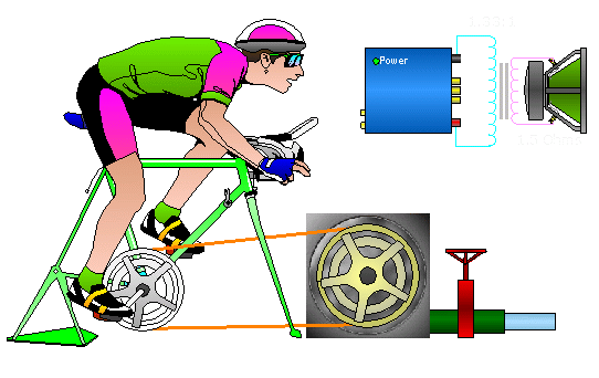
This set-up would be best suited to the body builder. The ratio would require more torque and less pedal speed. Again, an average rider may be able to pump enough water but it's not optimum for him. The smaller rider would not likely be able to produce enough torque with this combination. The amplifier (that's optimized for 2 ohm loads) would be able to drive it's rated power into a 2.7 ohm speaker if the transformer ratio is 1:1.33. The amplifier doesn't produce enough voltage to produce full power into the high impedance load. The transformer increases the voltage on the secondary (just as the pulley configuration increases the speed at which the pump is driven). This allows the amplifier to produce full power into the high impedance load.
 |

|

|
|

|