|
| Email Home Page |
|
|

|
| Email Home Page |
|
|
|
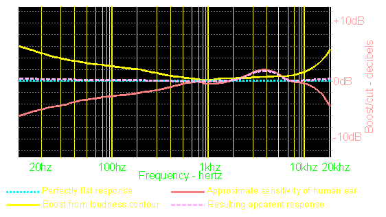
The loudness contour is employed in most audio devices which have a volume control. At low volume levels, the human auditory system is less sensitive to frequencies at the upper and lower ends of the audio band of frequencies. The contour INCREASES the level of the audio signal at those frequencies (where the ear's sensitivity is reduced) as the volume DECREASES. At the upper end of the volume control's range, the loudness contour has little or no effect. If your system is properly set up, the loudness contour (if properly designed/set) will keep the apparent levels of audio at all frequencies at a constant level throughout the volume control's range. The diagram below shows how the loudness contour compensates to make the audio response seem closer to flat. The red line shows the ear's sensitivity across the audio spectrum (just a rough hand drawn curve). The yellow line is the boost from the loudness contour. Some loudness contours only boost the low frequencies but to work properly, both ends of the audio spectrum should be boosted. The dashed cyan line is the aparent response that you'd ideally want (perfectly flat across the spectrum. The violet line is more like what you'd actually get with all but the most well designed loudness contour circuits.
 At low volumes, the boost would be greater than shown. At high volumes (above approximately 65% of the volume control's range), the boost from the contour would fade to nothing. If the loudness contour circuit is designed to work well and the gains are set properly, the bass and treble at all volumes should appear the same. Without the loudness contour, the bass and treble will sound weak at low volumes (if they were set to sound right at high volumes). The following link is a set of Fletcher-Munson curves for different volume levels. It shows how the levels of the different frequencies need to be boosted to 'sound' equal in volume. Use the 'back' button to return. The image is at Art Ludwig's site. He has a much more in-depth, detailed tutorial on acoustics for those who are interested.
Measuring Sound Pressure Level (SPL): When using an SPL meter, it may have a selector switch that allows you to insert a filter in line with the input signal. Some meters have dBA (decibels 'A' weighted), dBC (decibels 'C' weighted) and linear. DBA is used to simulate the levels 'heard' by humans at relatively low volume levels. DBC simulates human hearing at higher volume levels. Linear has no filter and indicates the actual levels present in the air. The following calculator gives the reading that the meter would display for A and C weights. They are referenced to 1000hz. If you enter 1000hz, it will return 0 which means that the level is the the same as the reference (which is 1000hz). If you enter most other frequencies, you will see that it returns a negative number. This means that the meter would return a level below the level at 1000hz (even if the actual levels were the same at the two frequencies). If the meter were set to linear, the SPL reading would be the same at all frequencies if the actual amplitude of the pressure in the air at all frequencies were the same. Remember that these values are the relative levels. If the actual amplitude of the SPL in the air were the same at all frequencies and is at a level of 100dB, the meter set on linear would return a value of 100dB at all frequencies. If you set it to dBA and produced a 100hz tone with a 100dB output, the level would read (100-19.1) or 80.9dBA. If you set it to dBC and produced a 100hz tone with a 100dB output, the level would read (100-0.3) or 99.7dBC.
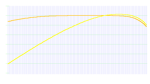
The following chart shows how the curves compare. The yellow line is dBA. Orange, dBC. You can see how much harder it would be to score a high SPL at low frequencies with the meter set to dBA.

Formulae Used:
|